State Parameters
This list describes many of the basic measurements made on the NSF/NCAR GV aircraft, also know as State Parameters. State Parameters give the scientist a measurement of the current state of a particular parameter.
These measurements are used by the scientists to have a better understanding of the physical measurements that their instruments are collecting. The State Parameters are used in conjunction with the data collected by the researchers to provide the most accurate data set possible. Measurements of altitude, latitude, longitude for example, give an exact location in space (and time) of the specific measure of a trace gas. The scientists can then infer on the physical, chemical and spatial characteristics of the measurement. The rest of the variables are used also by the scientists to make corrections or adjust their data sets depending on the conditions that the airplane experienced.
Aircraft & Meteorological State Variables
Meteorological and aircraft state measurements are made at various locations on an aircraft. The present radome measurements all have pressure sensors located in the nose area of the aircraft connected to the radome by semi-rigid tubing.
- Attack Differential Pressure (mbar)
- Sideslip Differential Pressure (mbar)
- Reference Attack Angle (deg)
- Static Pressure (mbar): This is the output from a calibrated absolute (barometric) transducer. The value is a static pressure corrected for local flow-field distortion.
- Dynamic Pressure (mbar): This is the output from a calibrated differential pressure transducer. The measurement is the difference between a pitot (total) pressure at location x and a static pressure.
- Total Temperature (C): This is the output of the recovery temperature from a calibrated temperature sensor at location x.
Aircraft Position, Velocity and Altitude
Global Positioning System (GPS) variables aboard RAF aircraft are gathered by a Novatel GPS receiver. It has the ability to track up to 11 satellites at a time but needs only 4 to provide 3-dimensional position and velocity data (3 satellites for 2-dimensions). The accuracy of the position measurements is stated to be 25 meters (horizontal) and 35 meters (vertical) under "steady-state conditions." Likewise, velocity measurements are within 0.2 M/s for all axes.
- GPS Latitude (deg)
- GPS Longitude (deg)
- GPS Ground Speed (M/s)
- GPS-Computed Aircraft Vertical Velocity (M/s)
- GPS Altitude (M)
Inertial Reference System (IRS) Variables
Honeywell HG2001GD Laseref SM Inertial Reference System (IRS) is used to obtain aircraft position, velocity, acceleration and attitude information.
- Latitude (deg)
- Longitude (deg)
- Aircraft True Heading (deg)
- Aircraft Pitch Attitude Angle (deg)
- Aircraft Roll Attitude Angle (deg)
- Aircraft Vertical Acceleration (M/s2)
- Inertial Altitude (M)
- Aircraft Ground Speed (M/s)
- Aircraft Ground Speed East Component (M/s)
All-Weather Gust Probe
![]() Content coming soon!
Content coming soon!
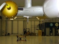
Laser Air Motion Sensor (LAMS-1)
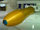 The Laser Air Motion Sensor (LAMS) is being developed for measuring the atmospheric wind speed and direction. For PREDICT, a prototype that measures the wind speed in the forward flying direction only has been installed on the NSF/NCAR GV aircraft. The LAMS measurement principle is based on the Doppler effect.
![]() Objects (in this case airborne particles) that move away from the detector are red shifted, and objects that move towards the detector are blue shifted. This shift can be measured optically using high power optical fiber laser systems that probe a small volume in front of the aircraft which is undisturbed and far enough away from the turbulence created by the aircraft itself. This laser radiation is partially backscattered from the moving airborne particles and mixed with a local oscillator laser field. When mixed on a photo detector, a signal is generated with a frequency that is proportional to the windspeed of the probe volume. An advanced system that is based on this prototype will be able to measures the windspeed and direction (3D) is being developed for future airborne missions.
Objects (in this case airborne particles) that move away from the detector are red shifted, and objects that move towards the detector are blue shifted. This shift can be measured optically using high power optical fiber laser systems that probe a small volume in front of the aircraft which is undisturbed and far enough away from the turbulence created by the aircraft itself. This laser radiation is partially backscattered from the moving airborne particles and mixed with a local oscillator laser field. When mixed on a photo detector, a signal is generated with a frequency that is proportional to the windspeed of the probe volume. An advanced system that is based on this prototype will be able to measures the windspeed and direction (3D) is being developed for future airborne missions.
Raw Icing-Rate Indicator (RICE)
 This is the output from a Rosemount 871F ice-accretion probe. It consists of a rod set in vibration by a piezoelectric crystal. The oscillation frequency of the probe changes with ice loading. When the probe loads to a certain point, the rod is heated to remove the ice. Its output voltage is related to the mass of the accreted ice.
Thermodynamic Variables
- Potential Temperature (K): This is a derived variable from the definition of potential temperature
- Virtual Temperature (C): The virtual temperature is the temperature of dry air having the same pressure and density as the air being sampled. It is a measure of the effect of water vapor on air density.
- Relative Humidity (per cent): Derived output of relative humidity from definition
- Mixing Ratio (g/kg): A derived variable that is expressed in terms of grams of water vapor per kilogram of dry air.
- Ambient Temperature (C): The ambient temperature (also known as the static air temperature) is calculated from the measured recovery temperature, which includes dynamic heating effects, using conservation of energy for a perfect gas undergoing an adiabatic (in this case, deceleration) process.
- Aircraft True Airspeed (M/s): This is a derived variable based upon a Mach number calculated from both the dynamic pressure at location x and static pressure.
- Water Vapor Pressure (mbar): This is a derived intermediate variable used in the calculation of several derived thermodynamic variables. The vapor pressure is obtained from the Goff-Gratch Formulation (1946).
Imaging
Forward Looking Camera
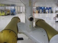 Anyone can access the forward looking camera images by access the PREDICT Field Catalog. A forward looking camera mounted under the right wing of the aircraft takes both images and high-resolution video throughout each flight. In the image to the right, the camera is the dark circle located between the two instruments.
Once you have clicked on the link above to the Field Catalog and are on the Research Products page, select the date(s) for which you would like to the images from the under-wing forward looking camera, and then click retrieve products.
From the results page, either an image from a specific time can be selected, or the image loop of all of the images taken from that days flight may be selected by clicking on the small video camera icon.
Left & Right-Side Cameras
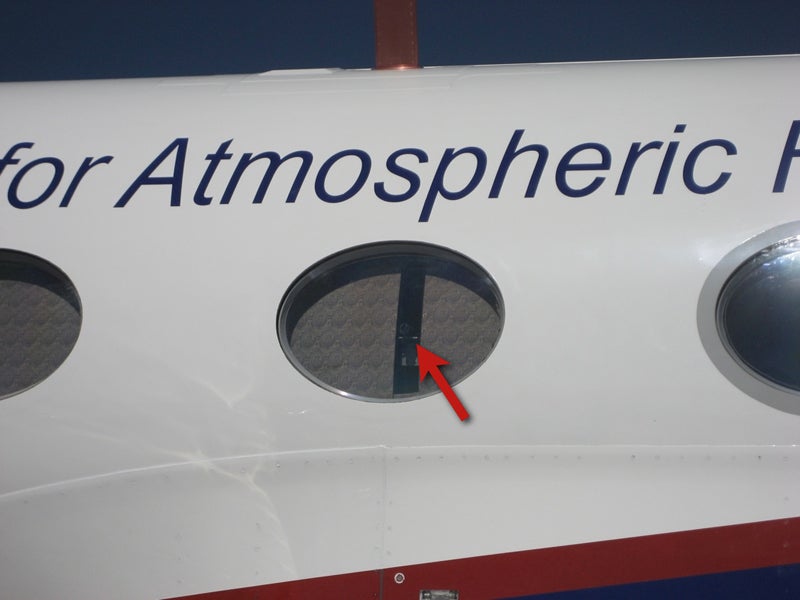 These cameras sits on the either side of the aircraft, pointing approximately perpendicular to the aircraft longitudinal axis, and slightly (about 5-10 degrees) downward from the horizontal. Each camera looks out of side-window and is mounted in the interior of the aircraft cabin. The cameras are a Point Grey Research hi-Res Flea - Color, 1024x768 resolution. The Navitar DO-412 lens has a focal length of 4 mm. The FOV is about 62 degrees horizontally and 48 degrees vertically with some barrel distortion.
Images were acquired once per second and stored as JPEG-compressed files of about 75 kB each. The UTC date and time are encoded in the filename as YYMMDD-HHMMSS.jpg. They are also annotated with the flight number and time in the upper left of the image and can be compiled into MPEG 4 movies.


