Vapor Pressure Instruments
Dew Point Sensors
 This measurement is the corrected dew point with respect to a plane water surface. Below 0º C the measured frost point is adjusted to dew point. The difference between the dew point and the frost point is derived from the Goff-Gratch (1946) equations for water vapor pressure over plane surfaces of water and ice. The accuracy of the conversion (one sigma) is 0.02° C over a range of 0º C to -80º C.
There are two Dew Point probes, located on both the right and left sides, just below and behind the nose of the aircraft.
GNSS Instrument System for MultiStatic and Occultation Sensing :: GISMOS
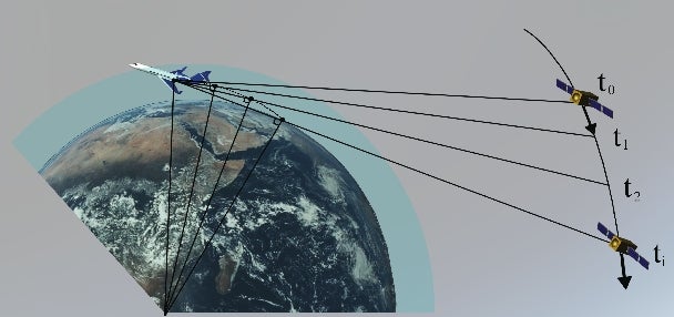
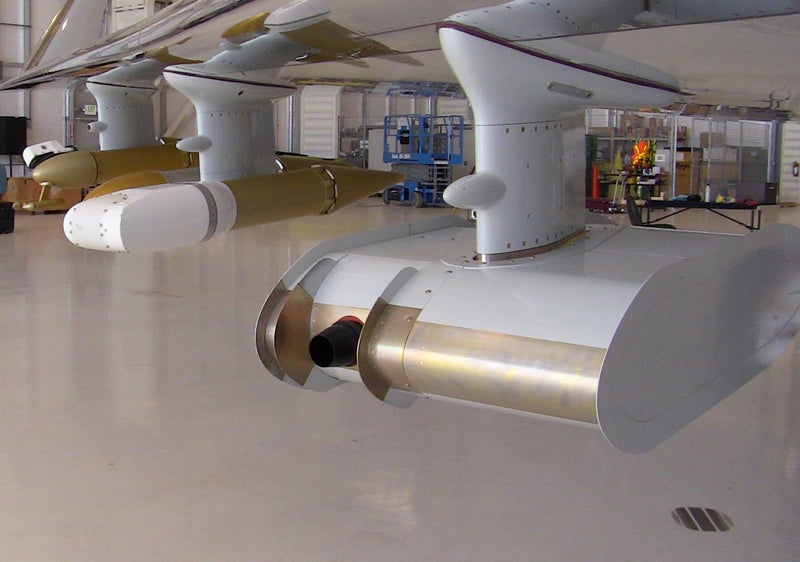
![]() The GISMOS system on-board the NSF/NCAR GV is designed to use occulted and reflected Global Navigation Satellite Systems (GNSS) signals to retrieve tropospheric water vapor, ocean surface roughness and soil moisture during long duration, high altitude, flights.
The GISMOS system on-board the NSF/NCAR GV is designed to use occulted and reflected Global Navigation Satellite Systems (GNSS) signals to retrieve tropospheric water vapor, ocean surface roughness and soil moisture during long duration, high altitude, flights.
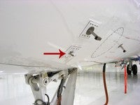
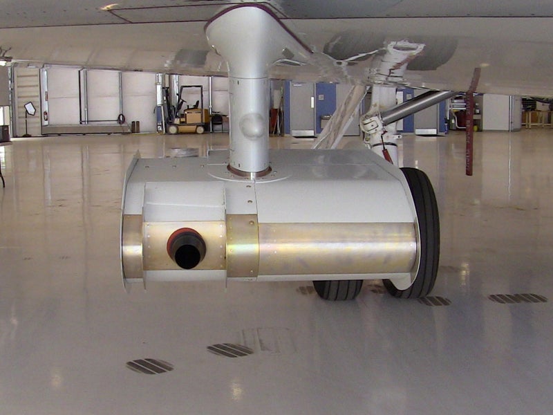
 Five antennas are provided for the GISMOS instruments. One is placed on the top of the aircraft fuselage, to record the direct signal for navigation. Two high gain dual frequency antennas that are specifically designed for the NSF/NCAR GV with a gain pattern focused toward the horizon are mounted inside the windows on the side of the aircraft (see image above), for occultation measurements. Another two antennas, receiving both left-hand (LHCP) and right-hand (RHCP) circularly polarized signals, will be mounted on the bottom of the fuselage for the reflection measurements.
- The GISMOS is monitored by Jennifer Haase, Brian Murphy & Alexandria Johnson
Tunable Diode Laser (TDL) Humidity
![]() The TDL setup consists of tunable diode laser light source, transmitting optics, optically accessible absorbing medium, receiving optics and detector/s. The emission wavelength of the tunable diode laser, such as the VCSEL, is tuned over the characteristic absorption lines of a species in the gas in the path of the laser beam. This causes a reduction of the measured signal intensity, which can be detected by a photodiode, and then used to determine the gas concentration, including water vapor, and other properties.
The TDL setup consists of tunable diode laser light source, transmitting optics, optically accessible absorbing medium, receiving optics and detector/s. The emission wavelength of the tunable diode laser, such as the VCSEL, is tuned over the characteristic absorption lines of a species in the gas in the path of the laser beam. This causes a reduction of the measured signal intensity, which can be detected by a photodiode, and then used to determine the gas concentration, including water vapor, and other properties.
The HIML, or air inlet valve, is mounted on the upper-right-side of the exterior of the aircraft, just opposite the VCSEL inlet.
- The Tunable Diode Laser is monitored by Teresa Campos.
VCSEL Hygrometer
 The Vertical Cavity Surface Emitting Laser (VCSEL) hygrometer measures water vapor concentration throughout the troposphere and lower stratosphere at high frequency (25 times per second), precision (<3%), and accuracy (5-10%). The wide dynamic range of the VCSEL is particularly well-suited for HIPPO Global where environments range from the warm and moist marine boundary layer in the tropics to the cold and dry stratosphere in polar regions.
![]() In addition, the VCSEL probes atmospheric moisture in an open-path configuration exterior to the aircraft (see picture at left). The lack of an inlet or tubing (which can create sampling artifacts for a "sticky" gas like water vapor) allows for the identification of highly resolved atmospheric layers in the horizontal and vertical. The heart of the instrument is a fiberized laser that passes near infrared light between two gold-coated mirrors that form the optical measurement cell.
In addition, the VCSEL probes atmospheric moisture in an open-path configuration exterior to the aircraft (see picture at left). The lack of an inlet or tubing (which can create sampling artifacts for a "sticky" gas like water vapor) allows for the identification of highly resolved atmospheric layers in the horizontal and vertical. The heart of the instrument is a fiberized laser that passes near infrared light between two gold-coated mirrors that form the optical measurement cell.
- The VCSEL Hygrometer is monitored by Mark Zondlo.
Water :: Liquid & Ice Instruments
2D-C Particle Imager (25µ)
 The Two Dimensional Cloud Probe, 2D-C, is an instrument developed by Particle Measuring Systems (PMS Inc., Boulder, CO) for the measurement of cloud and precipitation drop size distributions. These sensors are used primarily for the study of cloud microphysical processes, particularly the growth of cloud drops and ice crystals through aggregation, riming and coalescence into drizzle, rain drops, graupel or other forms of precipitation.
![]() The 2D-C record the two dimensional shadows of hydrometeors as they pass through a focussed He-Ne laser beam. The shadow is cast onto a linear diode array and the on/off state of these diodes is stored during the particle's passage through the laser beam. This information, along with the time that has passed since the previous particle, is sent to the data system and recorded for post-flight analysis.
The 2D-C record the two dimensional shadows of hydrometeors as they pass through a focussed He-Ne laser beam. The shadow is cast onto a linear diode array and the on/off state of these diodes is stored during the particle's passage through the laser beam. This information, along with the time that has passed since the previous particle, is sent to the data system and recorded for post-flight analysis.
Information about a particle's shape and size is deduced from analysis of the recorded shadow with a variety of pattern recognition algorithms. The 2D Cloud Probe measures in the range from 25 µm to 800 µm.
| Size range | 50µm to 800µm |
| Number of bins | 32 |
| Particle size resolution | 32 x 1024 bits |
| Sampling frequency | 5 hz average |
| Maximum particle velocity | 125 knots |
| Laser wavelength | 632 nm |
| Temperature | -60 to +50 degrees C |
| Altitude | 0 - 60,000 feet MSL |
Cloud Droplet Probe (CDP)
 The Cloud Droplet Probe (CDP), is a miniature, lightweight, low-power cloud particle spectrometer measures droplets in the range of 2-50 µm in concentrations as high as 2000 particles/cm3.
The CDP measures:
|
|
CDP is mounted on a wing pod under the right wing in the PREDICT instrument suite. The basic components and theory of operation is as follows:
- The air sample is passed through the laser beam and the particle scatters light in all directions. Of this scattered light, the photons which are scattered in the 4° to 12° range, are collected and directed to a 33/66% optical beam splitter.
- These forward scattered photons are focused through an optical mask and are directed to a pair of photodetectors (one of which receives 33%, one receives 66% of the scattered light). These photodetectors determine that the particle falls within the 'depth of field', and if acceptable, the photon pulses are then converted to electrical pulses, and are amplified.
- The resulting analogue voltage value is digitised and categorized into one of the 10, 20, 30 or 40 sizing bins.
- This data is transmitted to the on-board computer, via a RS232 serial packet, which is then logged and viewed by the instrument operator in real-time, using the Particle Analysis Display System (PADS).
Cloud Droplet Probe specifications:
| Size range | 2µm to 50µm |
| Typical sample area | 2.0mm x 180µm |
| Number concentration range | 0 - 10000 cm-3 |
| Number of size bins | 10, 20, 30 or 40. |
| Sampling frequency | 0.1s - 10s |
| Refractive index | 1.30 - 1.70 non-absorbing |
| Light collection angles | 4° - 12° |
| Air speed range | 10 - 200 ms-1 |
| Laser wavelength | 658 nm |
| Temperature | -40 to +40 ºC |
| Altitude | 0 - 50,000 feet |
Cloud Particle Imager (3V-CPI)
 The CPI measures the size, shape and concentration of water drops and ice particles in clouds in the size range of 15-250 µm, with the images having a nominal 2.3 µm resolution. Image analysis and data processing software provided with the probe takes particle size information, including area and volume, and ice crystal habit classification from the images to produce histograms. The 3V-CPI is especially suitable for use in ice and mixed phase clouds which typically have relatively low (compared to water clouds) particle concentration of 1000/L. The CPI may be used in much higher particle concentrations, but under these conditions while particle spectra are reliable, absolute particle concentrations are not due to coincidence errors in the particle detection system.
 The CPI uses a 3-laser system for detection and imaging of particles passing through the instrument's sample tube. The detection subsystem uses two continuous beams, which are ribbon-shaped and create a cross section of approximately 2.4 x 0.5 mm. The beams are aligned to intersect and to define the sample area of the probe. Scattered light from each beam falls onto a separate detector, and a particle is detected when a pulse is simultaneously recorded from each detector. When a particle is detected, the imaging system is triggered, and the sample area is illuminated with a single pulse from the imaging laser.
 ![]() The imaging optics focus this light onto a 1 mega pixel charged coupled device (CCD) camera. Once an image has been obtained, this is analysed in real time by the data system, areas of interest are identified and cropped from the frame. Some preliminary image analysis takes place, and the images along with data from the detection system and probe housing information is saved to disk. Subsequent post processing produces size spectra, number distibution and habit classification information.
The imaging optics focus this light onto a 1 mega pixel charged coupled device (CCD) camera. Once an image has been obtained, this is analysed in real time by the data system, areas of interest are identified and cropped from the frame. Some preliminary image analysis takes place, and the images along with data from the detection system and probe housing information is saved to disk. Subsequent post processing produces size spectra, number distibution and habit classification information.
PMS Liquid Water Sensor (King) (PLWC)
 PMS Liquid Water Sensor (King probe) is used primarily for the study of cloud microphysical processes and in icing studies. It uses a heated wire to measure liquid water content (LWC). This instrument is relatively simple and accurate (≈ 15%) for higher liquid water content (LWC); however, accuracy is diminished at lower LWC since the baseline (the clear-air signal upon which the in-cloud signal is superimposed) is dependent on airspeed, temperature, and pressure. Droplets between 5- and 40-μm diameter are efficiently sampled.
Small Ice Detector (SID-II)
 The Small Ice Detector classifies particle size and shape of water droplets and ice crystals in ice and mixed-phase clouds. The probe achieves this particle classification at rates of several thousand particles per second by capture of the spatial pattern of light scattered by individual particles as they pass through a focused laser beam orthogonal to the flight direction. The SID-II uses a dedicated hybrid photodiode (HPD) device to capture the spatial pattern across 24 radial wedge pixels.
 ![]() This particular instrument has enhanced sensitivity though the use of a higher power laser, improved optical design, and a 32-anode photomultiplier and optical-fibre relay in place of the HPD detector because it has been customized for use on the NSF/NCAR GV.
This particular instrument has enhanced sensitivity though the use of a higher power laser, improved optical design, and a 32-anode photomultiplier and optical-fibre relay in place of the HPD detector because it has been customized for use on the NSF/NCAR GV.
Read more about the NSF/NCAR GV Small Ice Detector II.
Temperature Instruments
Microwave temperature Profiler (MTP)
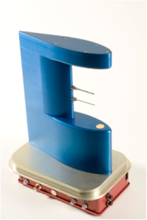
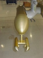
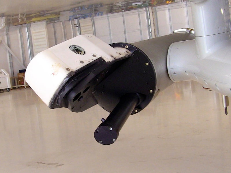
 The Microwave Temperature Profiler (MTP) is a passive remote sensing system that provides researchers with atmospheric temperature structure above and below the aircraft. Basic components of the MTP are a receiver which measures emission by oxygen molecules at three microwave frequencies and a scanning mirror which views the emission at 10 elevation angles. The three microwave frequencies have different penetration depths so the sensor is able to "see" to different distances from the aircraft with each channel (the plastic window covering the sensor shown in the attached photo is transparent at microwave frequencies).
 ![]() Different effective viewing distances are also achieved by scanning in elevation. With three frequencies and 10 elevations angles, 30 separate measurements of brightness temperature are acquired with each 18 second scan. Calibration is performed as the scanning mirror views an internal target during each scan. A statistical retrieval algorithm is applied to convert the brightness temperature observables into temperature as a function of altitude.
Different effective viewing distances are also achieved by scanning in elevation. With three frequencies and 10 elevations angles, 30 separate measurements of brightness temperature are acquired with each 18 second scan. Calibration is performed as the scanning mirror views an internal target during each scan. A statistical retrieval algorithm is applied to convert the brightness temperature observables into temperature as a function of altitude.
- Julie Haggerty is the lead scientist for the MTP.


