UPDATE, 2019
Abbreviations
HFT - Heat flux plate (REBS)
EC-5 - Soil moisture probe (Decagon)
TP01 - Soil thermal properties sensor (Hukseflux)
Guidelines
- No soil installation will be the same, due to soil composition and structure. Our usual installation is trying to measure the near-surface heat flux into/out of the soil. Since we are interested in seeing a diurnal variation (same as the other terms in the surface energy balance), we chose a shallow depth (5cm) for our heat flux plate. Other measurements are to be representative of the 0--5cm layer above this plate.
- The soil moisture and thermal properties probes we use that are influenced by a region above and below the probes, and may have "edge effects" from the surface. We are attempting to quantify this region, though we suspect that the distance depends on soil thermal and electrical properties. However, recent work using our data (Wu et al., 2018) indicate that significant changes in properties occur even within this 0-5cm layer. For GRAINEX and the beginning of RELAMPAGO, we changed from installing these 2 sensors at 5cm to 2.5cm -- the middle of the 0-5cm layer -- however, we found that the sensor read consistently low, indicating that the EC5 was sensing the air above the soil. We have returned to placing this sensor at 5cm.
- Wu et al. 2018 also show that horizontal gradients in the soil can be significant, suggesting that the soil probes should be as close to each other as possible. However, it is possible that installation and operation (RF or heat pulses) of one probe could disturb another. Thus, we now identify a soil plot and install each of the 4 probes in a corner of this plot. By eye, we attempt to select a plot representative of the local area (e.g. that observed by a nearby radiometer), with uniform conditions across it, i.e. not to have one under a clump of vegetation and the rest in bare patches.
- The soil sensors will be connected to a solar-panel powered mote that casts a shadow. Thus, we place this mote to the north (in the Northern Hemisphere) of our sampling plot.
- In general, probes are oriented vertically to avoid pooling of water on top of them. This necessarily increases their vertical sampling. The exception is the heat flux plate, that must be oriented horizontally (and with the white dot on the top surface).
- Gsoil will be corrected by the storage term, for which the most important measurement is Tsoil.
- These probes still require knowledge of the soil bulk density, so it is necessary to take at least three soil cores nearby during the project. These cores can also be processed for comparison with the EC-5.
- In very saline soil, the EC-5 calibration can be off and will require calibration using manual cores.
- With these guidelines, the generic layout for sensors is:
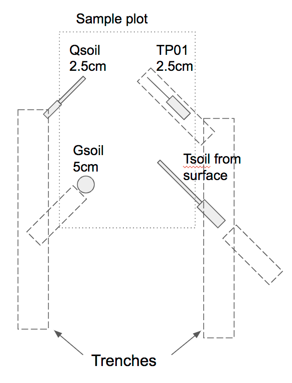
Sample installation
- Chose a location that you deem "representative" of the surrounding landscape. We should be making (at least) triplicate samples, at different plots, but usually only have one. Carefully scrape off any loose (normally organic) material until you reach more solid soil from the trenches mentioned below, and set to one side. After installation, replace this material as best you can to match the surroundings and hide your work.
- We start by digging trenches on either side of the sample plot. Each trench will hold the cables from the probe and be used as the starting location for the sensor installation. The trench is usually the width of the trowel and goes down to a bit more than 5cm. Lay the orange plastic bag flat on the ground nearby to place the dirt that is removed.
- At the end of one trench, insert the EC-5 Qsoil probe, pointing in at about 45 deg (azimuth), with the probe vertical, the lettering upside down, and the midpoint at a depth of 5cm (The diagram above was drawn before we found that 2.5cm is too shallow for many deployments.)
- Back along the same trench, dig a short trench at 45 deg and square off (vertically) the side towards the center of the plot. Using the bent table knife, cut a horizontal slot a bit wider than the HFT-Gsoil sensor at a depth of 5cm (indicated by a black line on the knife handle). Although you don't want to compact the soil much, it often is necessary to lift up and push down the knife to make a slot high enough for the HFT to fit in. Push the HFT into this slot as far as possible, having the white dot facing up.
- Guide the cables to the north end of the trench and backfill using the dirt removed.
- At the end of the other trench, remove a "clod" to a depth of about 1cm (if possible), at an angle into the plot of 45 deg. You now want to make a slot to slide the TP01 down into. Use the bent knife to dig a big enough slot for the white part of the TP01, then use the trowel to cut a slot for the flexible TP01 foil. Place the TP01 into this slot, making sure that the foil is straight. Sometimes, shoving a pebble against the white part helps to keep everything aligned. You also want the TP01 to be vertical, centered at 2.5cm depth, which means that the top of the foil will be about 1cm below the surface. Replace the "clod" on top of the probe.
- Back along the same trench, square off a vertical face at an angle of approximately 45deg, facing the plot. Aligned with this face, dig a short trench on the opposite side of the main trench. Place the Tsoil probe into the short trench, with the bump on the grey plastic handle on top. Push the probe into the squared-off face, trying to have the bump level with the surface.
- Guide the cables to the north end of the trench and backfill using the dirt removed.
- Try to arrange the surface to eliminate cracks and to appear similar to the surrounding area.
- Dress the cables to the mote and cover above-and-near-ground cables with plastic sleeving.
Manual soil samples
- Soon in the project, take at least one soil core to measure the bulk density of the soil. During the project, at least another 2 cores should be taken to have a minimum of 3 points to compare soil moisture to the EC-5.
- Set up the corer tool to sample 3-6cm (top ring is 3cm, that will be discarded, next ring is 3cm, that will be kept). Use a bit of grease on the threads before screwing the corer to the handle. Unscrew the corer about a 1/4 turn to avoid jamming the threads. Pound in corer tool until the silver ring is flush with the top of the soil, or even a bit deeper. Break the core from the bottom by rocking (not twisting) the corer tool. Remove core. (In sand, it may be necessary to undercut the sampler before removal to support the core from underneath.) Carefully unscrew the core from the handle.
- Weigh empty tin (with lid) and record (the "tare" reading), along with time/date/location of sample and the tin number. Always tare the scale to 0 before each weight measurement.
- Insert pusher cylinder into the bottom of the corer and slowly push out the first brass ring (with the soil) through the top. Using a knife/hacksaw blade/etc., cut this top ring and core off and let fall. (Later, I usually refill the cored hole with the soil from this ring.) With the corer above the empty tin, push out the next brass ring and let fall into the tin. You can keep the ring in the tin (through all the later processing), but it usually is simpler to remove it, keeping as much soil as possible in the tin. Cover the tin, reweigh and record (the "wet" reading).
- Clean the tool, wiping down all pieces with the hand cloth to set up the tool for the next sample.
- Later, uncover the tin and place in oven (setting 4.7 gives about 105 degC) to dry for 24hrs. After drying, reweigh (with lid) and record (the "dry" reading"). Enter all readings in the Wiki logbook for the project.
Images
