Introduction
Microfronts95 was a study of the small-scale characteristics of atmospheric frontal structures which was carried out in South-central Kansas. It used the ASTER (now ISFF) facility and one CLASS (now GLASS) system from ATD.
This document is a standard product of NCAR/EOL/RTF which gives an overview of the measurements taken using the Integrated Surface Flux Facility (ISFF) and conditions during this experiment.
Data Access
ASTER data are stored in two forms:
- 5-minute averages of first and second-order moments of calibrated data. We recommend combining these to obtain more statistically-significant averages over longer time periods. These statistics in NetCDF form are in this directory.
- 1, 10, or 20 sample/second uncalibrated values. Software is maintained at SSSF to generate calibrated time series on demand using the most current calibration routines.
Also available is a computer-readable log of comments noted by ASTER personnel. The logbook can be read here (sorry, some comments are garbled and this version cannot be searched). For access to the ASTER data, please contact SSSF.
Location
This experiment was located in rangeland near De Graf, Kansas (about 15 miles north of El Dorado, and 35 miles northeast of Witchita). This site had gently rolling terrain, with no major obstacles within several kilometers. The positions of various sites were:
- CLASS: 37deg 59' 59.5"N, 96deg 51' 19.7" W
- ASTER Trailers: 37deg 59' 55.1"N, 96deg 51' 19.7" W
- South Group (transformer): 38deg 00' 15.4"N, 96deg 51' 19.7" W
- North Group (transformer): 38deg 00' 21.4"N, 96deg 51' 10.8" W
Sensors
The MICROFRONTS Tower Layout shows the locations of the ASTER towers used for this program. The south tower group was located approximately 540m north of the ASTER trailers and the north tower group was another 300m northeast of the south tower group. The critera for selecting these locations were:
- Maximum crosswind (the expected prevailing wind direction was NW) separation between the two tower groups to enable sampling in two regions of convective rolls (which are oriented along wind).
- Good fetch for winds from the W through N, and also from the S. (Note that the sensors should not be in the wake of their supporting towers since the booms point to the NW.)
- Towers located near local ridges in the topography to give the sensors good exposure.
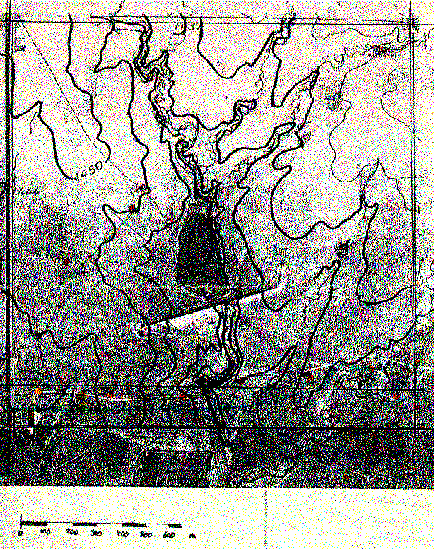
I have prepared a crude map of the section (1 square mile) which has been useful to document the site. This was prepared by photoenlarging the USGS 7.5" topographic map so that it could be overlaid on a photocopy of a blueprint of an aerial photo of the site (taken before the retention dam was built). I've hand embelished this map with red dots for the tower sites, yellow for the trailer locations, and orange for the oil pumps and tanks. (Actually, the towers were at black dots on the thin green line, i.e. the South Towers were about 60m East of the red dot.) A blue line indicates the power line and a high tension line is visible on the lower right. I've put a scale in meters along the bottom, again by hand. The height contour going through the North tower location is 1440 feet and other contours are at 10' intervals.
The MICROFRONTS Configuration documents which sensors were deployed on each of the towers. Each sensor is labeled by the quantities it measures, its name, its height on the tower, and the tower name. Sensor Table lists the type, manufacturer, and other specifications of the sensors used for this project. The south tower group had the majority of sensors, with up to six levels of mean temperature and humidity sensors, three levels of mean wind sensors, two levels of turbulence sensors (three-dimensional sonic anemometer, temperature, and humidity sensors), radiation sensors, a precipitation gauge and soil temperature and heat flux. Both turbulence levels also had mounting locations for hotwire anemometers, though the arrangement of these anemometers changed during the program (see the logbook). The north tower group had fewer sensors, with only two levels mean temperature/humidity sensors, three levels of mean wind sensors, and one sonic anemometer and temperature sensor for turbulence. The setup allowed for a hotwire anemometer to be deployed with this sonic anemometer, but was never used during the program.
The non-standard (not included with ASTER) sensors used for this program were:
- Two hotwire anemometers mentioned above to measure direct TKE dissipation rates and to provide high resolution wind speed data through fronts and microfronts.
- A "veggie" meter mounted at 3.5m on the south sonic anemometer tower downward looking to measure the greenness of the vegetation by measuring the reflected light in two infrared wavelengths which are absorbed and not absorbed by chlorophyl.
- Four downward-looking infrared radiometers (Everest, two portable) to measure variations in the surface temperature.
- A Licor carbon dioxide sensor with an inlet at the 3m south sonic anemometer for measuring CO2 fluxes. This sensor operated for less than a week.
- An aspirated temperature and humidity sensor which was tested for use with PAMIII.
Known Instrument Problems
The first half of the program had several periods of heavy rain and/or snow. Many of the sensors did not perform well in these conditions. Otherwise, most of the ASTER sensors performed normally. One of the hotwire bridge circuits died during the early part of the program, so it was never possible to operate 3 wires.
Albedo from the radiometers should give a good indication of when snow was on the ground (most of the time). Surface conditions (including snow depth) often were noted in the system logbook.
Known instrument problems:
- The fast-response temperature probes broke during almost all of the precipitation events, but were replaced once the towers had dried off. This is normal for these probes. During these periods, the sonic anemometer virtual temperature can be used.
- The propeller-vane anemometers sometimes failed completely. This probably was caused by moisture on the serial connector or in the serial cable. Additionally, prop.10m.S and prop.3m.S gave low, or 0 speeds until day 76. The cause was later isolated to faulty components in the speed encoder. For prop.10m.S, about 20% of the time the speed was 0, and another 25% had low speeds. Unfortunately, this failure mode is difficult to detect on a sample-by-sample basis, so bad values will be present in the archived data. Bad data can be found by comparing the speeds to those from prop.5m.S, or from the sonic anemometers.
- There was only one krypton hygrometer during most of the program. For the first two weeks of operations, one was being repaired (replacement of a weak detector tube) for a failure during pre-calibrations. A few days before it was sent out to the site, the other instrument failed (source tube died), presumably because of excessive cold and moisture. This was fixed and arrived back on site during the last week of operations.
- The Everest radiometer, Tsurf.east.dark, read both too large and too small intermittenty throughout the program, which probably was due to a problem in either the electronics or cable. This affected about 1/4 of the data. Only use these data if the readings are similar (within 4 C) of Tsurf.west.dark.
- There was an offset in psp.out, which appeared to have been due to a loose connection in the junction box at the darkhorse. This connection problem was discovered during the last week of operations. The data will be corrected by assuming that this should read 0 at night.
- The pyg and psp fans, used for the first time for this program to keep the domes clean, died. This should not affect the data from these sensors.
- Two net radiometers, a Q6 and a Q7, were used, but often had different readings (Q7 less than Q6). The cause of this will be studied further by comparison to the sum of the four radiation components.
- The veggie meter was turned off and on during the first week of operations and later left on until the battery died. The battery was replaced at least twice during the program. The readings appeared to be low after the second battery replacment.
- Data from the fast temperature sensor on the north tower, t.gill.10m.north, were lost in the middle of the program because water shorted out its electronics and it took a while to discover that the gill stopped digitizing its signal after it had dried out.
- The Licor CO2 sensor died after a heavy rain midway through the program (after operating for less than a week). It had to be repaired by the factory.
Refer to the logbook for more details on sensor operation.
One hotwire was deployed during the last part of setup using one of the Friehe bridges (#1). It ran until an unexpected heavy rain destroyed the (only) probe. Several days later, another probe was deployed. While testing yet another probe with the TSI electronics, that probe died, so we were suspicious of the TSI electronics. The other Friehe bridge (#2) was not working, but recovered after an adjustment was made in its electronics (offset null). At the beginning of the second week of operations, a wire was connected to the Friehe #2 bridge, but it was found that the Friehe #1 bridge had died. Despite extensive work on #1 (replacing all active components), it never recovered. Therefore, data were taken during using #2 for most of the time from week 2 through the end of operations. During the last week of operations, the TSI bridge was tested again and found to work, so about 5 days of data are available with two wires (both on the south towers, and mostly both at 3m in two orientations).
Chronology
Julian Day: Action
- 051: Archiving Started.
- 061: Props at 3m.S and 10m.S switched to work on erratic prop behavior.
- 061: Reoriented atik.3m.S.
- 067: Licor CO2 sensor deployed, but not reading correctly.
- 068: Licor CO2 sensor reading reasonably.
- 071: Licor CO2 sensor died.
- 075: Artificial surface (black plastic) around S towers next 2 days.
- 076: Krypton #1133 deployed at 3m.S; #1101 had died.
- 077: Krypton #1133 moved to 10m.S; This starts ops2.
- 078: Tsoil.C dug up for use in measuring canopy temperature; This starts ops3.
- 085: Krypton #1101 reinstalled after factory repair.
- 088: Tires, etc. removed from S towers.
Data Processing Notes
- The sonic anemometer data have been processed using a tilt correction which fits the mean wind to a planar surface, which ideally is parallel to the actual surface of the ground. Since the terrain was more complex than a simple plane at this site (both North and South tower locations), the statistics will still contain some residual terrain-induced effects.
The tilt plots show somewhat surprising behavior. The two 10m levels agree quite well, with large (2 degree) angles which generally agree with the slope. However, the 3m.S sonic is nearly flat.
- The fit to atik.3m.S was done over three time periods, since a mechanical adjustment was done on day 61 (see logbook comment #50) and the bias in "w" apparently changed after a failure on day 73. A change in pitch of 0.8 degree is seen between the fit from Days 52-60 and Days 62-73 (about equal to the logged change of 1 degree). The bias changed by about 7 cm/s for Days 74-90.
- The bias on atik.10.S was adjusted between Days 52-81 and Days 82-90 (see logbook #170).
- One fit was done for gill.10.N for all days (52-90).
- The sonic anemometer data have been despiked using the current adaptive despiking routines.
- A crude calibration for the Licor was determined by noting that at the end of day 69, zero appeared to be 0.8 V, and the signal was about 2.13 V. It was guessed that the CO2 concentration corresponding to this voltage difference of 1.33 V was 380 ppmV, which is probably good to about 10%.
- A crude correction for the psp.out failure was made by examing the readings every day before dawn and after dusk, and subtracting a bias which was linearly interpolated from these readings. This bias varied between +/- 70 W/m2. The residual error should be less than 20 W/m2.
- Several tests to determine biases in the mean temperature and humidity sensors were performed throughout the experiment. These are described in Psychrometer Bias Analysis. The results do not show consistent biases or even consistency between the different methods. However, most of the biases were within the expected error for these sensors (0.1 C, 2% RH), so no corrections to the data were applied. If greater accuracy in the profiles is needed, we recommend looking at near-neutral profiles nearby in time.
Daily Weather Plots
The following plots summarize conditions during each day of the project. Each plot covers one Julian day (0000-2359 GMT) and is labeled with time in GMT at the bottom and local time (CST) at the top. The top panel displays temperature and specific humidity from the 3m south tower, pressure, and precipitation rates (if present). Below that is a plot of wind speed and direction from the 10m south tower, with dotted lines showing the directions in which flow distortion by the towers should not be a problem (there may be more). The next panel shows net radiation measured at the south tower, and sensible and latent heat flux from either 3m or 10m on the south tower. (Frequently one of these sensors was bad due to the Krypton hygrometer problems or breakage of the fast temperature probes.) The bottom panel shows the Monin-Obukhov stability parameter, z/L, the friction velocity, u*, and the Bowen ratio calculated from the 3m or 10m south data. Since these fluxes and derived parameters are based on smoothed, 5-minute average statistics, they should not be used quantitatively and are only shown for guidance in selecting periods to analyze further.
Instrument Status Plots
These plots show when there were gaps in the data collected for each instrument group. These plots do not indicate when sensors were providing good data, only that a signal was recorded.
Other plots
- Statistic comparison plots:
- Soil Moisture
Field Logbook
A computer-readable field logbook of comments by NCAR and other personnel is available in read-only html form.
