HIAPER Cloud Radar (HCR)
The HIAPER cloud radar (HCR) is an airborne, polarimetric, millimeter-wavelength radar that serves the atmospheric science community by providing cloud remote sensing capabilities to the NSF/NCAR HIAPER Gulfstream V aircraft.
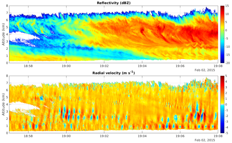
HCR provides unique observations of the formation and evolution of clouds. Its high sensitivity allows for the precise detection of liquid and ice clouds, aiding our understanding of the effects of clouds on the regional and global weather. Derived scientific products, such as melting layer altitude, convective and stratiform echo type, or hydrometeror particle identification, provide additional information on the observed cloud and precipitation processes.

Specifications
HCR is mounted in the aircraft's underwing pod. A lens antenna illuminates a rotatable reflector, which allows for 240° cross-track scanning as well as staring, for example, at zenith or nadir. In staring mode, the beam is stabilized every 20 ms for changes in roll and pitch angles caused by platform motion. Measurements such as reflectivity, velocity, and dual-polarization variables are computed with a resolution of ∼20 m in range and a temporal resolution of 10 Hz.
| Parameter | Specification |
| Antenna | 0.3 m, lens |
| Antenna gain | 45.7 dBi |
| Beamwidth | 0.73 deg |
| Transmit frequency | 94.4 GHz |
| Transmit wavelength | 3.2 mm |
| Transmitter | Klystron |
| Peak transmit power | 1.6 kW |
| Pulse width | 0.2 - 1.0 μs |
| Pulse repetition frequency (PRF) | up to 10 kHz |
| Range resolution | 20-180 m |
| Unambiguous range | 15 km, PRF=10kHz |
| Receiver bandwidth | 20 MHz |
| Receiver noise figure | 8.9 dB |
| Sensitivity | -37.0 dBZ at SNR=-10dB, 1 km, and 256 ns pulse |
| Typical reflectivity uncertainty | 1-2 dB |
| Unambiguous velocity | +/- 7.75 m/sec, PRF=10kHz |
| Typical radial velocity uncertainty | 0.2 m/s at W=2 m/s |
| Typical dwell time | 100 ms |
Contact
NCAR/EOL HCR Team. (2014). HIAPER Cloud Radar (HCR). UCAR/NCAR - Earth Observing Laboratory. https://doi.org/10.5065/D6BP00TP.