A key innovation for TRAM operation was implementing constant speed control, though it took several years (with hardware changes) to get this operating properly. Prior to implementing this, the DC motor on the trolley would operate at constant voltage, causing it to speed up on cable runs (especially downhill) and slow down (often dramatically) on turns. Speed varied from 0.5 to 8 m/s on every turn, which mechanically stressed all components of the system. Pieces literally fell off the trolley and MTBF was low. With constant speed control, speeds are now 2--4 m/s (settable) and much more reliable operation has been achieved.
The speed set-point can be changed from the DSM (see below). This would allow multiple trolleys to operate on the same cable, by adjusting speeds to avoid collisions. At present, there is only one trolley, so multiple trolley operation has not yet been implemented.
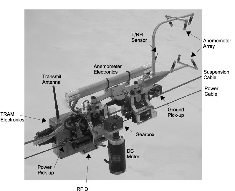
Mechanically, the trolley consists of two wheel clusters with a flexible link in between and stuff hanging off from the side paniers or on the top of the cluster. Each cluster consists of 3 wheels forming an inverted Y to grab the suspension cable and another 2 wheels below that engage the lower metal flange on the turns to fix the trolley orientation. All but the top wheel in each cluster are spring loaded to maintain a good grip as the support changes diameter between the suspension cable and the turn top tubing. The drive wheel (top of the rear cluster) has an extended shaft that rotates on stainless steel ball bearing sets. All other wheels rotate on bushings on fixed axles. The drive shaft attaches to the motor through a toothed coupler and a 90-degree 2:1 reducing gear box (to provide more torque through high friction areas). Guidance slots on the cluster frames are lined with a Delrin block to prevent wear on the frames' aluminum.
The two wheel clusters are connected by a flexible linkage. To allow the trolley to follow turn direction changes, this linkage pivots at the top of each cluster (again through a bushing and captive bolt acting as a fixed axle). To be able to adapt to pitch angle changes, it has a middle pivot point with two internal opposing springs providing some resistance.
Electrical pick-ups are two spring-loaded copper leaves that grab the power cable and two (one front, one rear) spring-loaded copper wheels to roll along the top of the suspension cable. During TRAM's first use in a wilderness forest, there were concerns about sparks generated by the slider pick-up. The roller wheels reduce the number of spark generation points, but even so, the sparks generated by the power pick-up were observed at night not to travel more than a few cm. The spring-loaded roller wheels have an additional advantage of keeping the wheel clusters aligned with the cable, even during cable pitch changes.
The top wheel of the front cluster ("idler wheel") also has an axle shaft that connects to the trolley speed counter (see next section). This was not mounted in the above photo.
All components of the trolley (wheels/axles/structure/electric pick-ups/etc.) were built from scratch by NCAR/EOL/DFS.
Balance of the trolley is rather critical to maintain even wear on the wheels. Currently, there is a brass counterweight with the trolley electronics box to balance the DC motor. Some trim brass and copper weights are also sometimes used. This rear cluster balance changed with the removal of the CO2 sensor and the installation of the Novatel GPS antenna. The front cluster is now balanced just by the addition of a U-bolt plate on the right side. Balance should be checked as part of each outing.