RAF Ozone Photometer
The core part of the Ozone Photometer (called here OP-1) was designed and developed by Proffitt Instruments, Inc. and has flown hundreds of hours on a variety of airborne platforms. The particular instrument operated by RAF is a re-packaged and modified version of the Proffitt photometer delivered by Psysical Sciences Inc. as part of the HAIS instrumentation package for the GV aircraft. The modifications to the core design include dual power capability (110VAC / 28VDC), IRIG time stamp interface and real time ozone mixing ratio output for displaying on the GV data systems.
Upon delivery the instrument has demonstrated a negative offset in the produced mixing ratios and was returned to PSI for further work. PSI concluded that the cause of the negative offset was a leaking stream selection valve, and proceeded to manufacture an O-ring isolated stand-off for the valve motor and deliver the instrument to RAF.

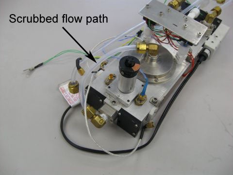
However, the issue of negative offset has not apparently been solved. Further analyses using a second Proffitt Instruments photometer (we call it here the OP-2) indicated that the issue of negative offset is most likely caused by the difference in the temperature and flow between the sample flow path and scrubbed ozone-free flow path. This conclusion has been confirmed experimentally by heating and cooling the Teflon tube zero-ozone flow path that can be seen on the picture on the right, and observing the changes in offset. The changes occur nearly immediately when the Teflon line changes temperature, and the offset can become positive or negative depending on whether the teflon line was heated or cooled.
The OP-2, on the other hand, had a different design of the zero-ozone flow path implemented at the time Proffit Instruments investigated the reasons for the negative offset. The flow path on OP-2 is constructed of a machined aluminum block and is in solid contact with the instrument cell body. This allows the flow path to maintain temperature very close to that of the sample flow path, and OP-2 does not exhibit the negative offset issue.
Another issue that was identified with OP-1 that was changed in OP-2 is the flow difference between the two flow branches; the flows were adjusted much closer in the OP-2.
Several minor issues also were identified when OP-1 was tested upon delivery:
- Minor leaks existed in several locations on the instrument, including thermistor pass-throughs and the newly designed motor stand-off and O-ring shaft seal;
- Temperature controller for the cell heaters is excessive and can pull down the power voltage;
- Processing software is unable to process files in excess of 2-3 hour duration.
The instrument as delivered was packaged in a large aluminum enclosure that takes up approximately 10U of rack space.
Planned re-packaging, upgrades and modifications

The location of components and the fairly small volume occupied by the instrument components inside the enclosure lead to an idea of miniaturizing the instrument in order to make it more deployable, particularly on the GV where rack space is always at a premium.
Re-packaging
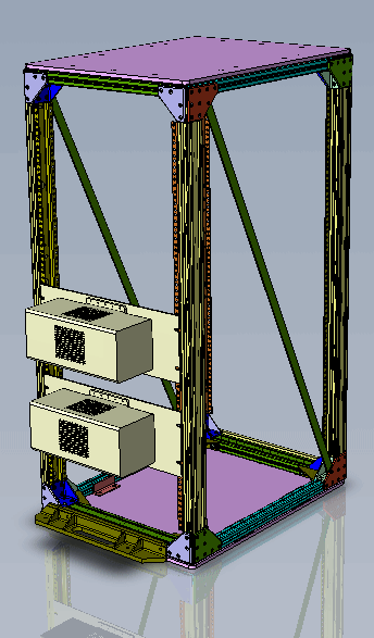
In short, the instrument can be separated into two major assemblies, the cell and the electronics. These two assemblies can be packaged into a DSM-like configuration and mounted separately on a face side of a GV MCE rack, interconnected by the signal and power cables, as shown on the right. This configuration would allow the instrument to be mounted on the rack without competing for internal rack space with other instruments, provided that the rack is not at the limit of its overturning moment. The instrument would need a standard HIMIL inlet with a pass through 1/4" Teflon intake line.
Upgrades
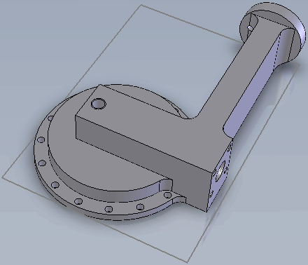
In order to resolve the negative offset issue the instrument is going to be modified to the same configuration as OP-2 with a machined aluminum flow path, shown below. This modification will allow for constant temperature for both branches of internal flow and incorporates an adjustable, calibrated flow restrictor that balances the flow between the scrubbed and sample flow paths.
The minute leaks throughout the instrument will be repaired by upgrading the thermistor pass throughs with hermetically sealed ones that were not available at the time the instrument was built.
The O-ring isolated stand-off that was installed under the valve motor will be removed along with its mounting plate, which turned out not to be concentric with the valve and caused leaks. The two parts will be replaced with a taller motor mount that is O-ring sealed to the cell body and separately evacuated, preventing the possibility of leaks.
Modifications
The instrument's detector boards (electrometers) were assembled using sub-optimal methods. After a thorough analysis by Proffitt Instruments and RAF electrical engineer, an improved design has been developed and manufactured. These boards will undergo comparative testing alongside the old boards, and will hopefully improve the signal-to-noise ratio of the detector circuit.
Separation of the power supplies and the PC-104 data acquisition computer from the cell with its low-voltage electrometer circuitry will hopefully further isolate the detectors from electrical noise.
Future improvements
There are several other upgrades that can be implemented in the future to improve the performance and maintainability of the instrument. Thes include re-design of the electrometer boards using sigma-delta converters, the technology that was not available when the original design was completed; replacement of the prototype circuit boards with PCBs; improvement to the motor control circuitry, etc. These changes are optional and may be considered after the instrument is operational.
Comments, questions and answers
| Question | Answer |
| The machined aluminum flow path is a great way to keep the temperature stable. Will this be a sheath for the PFA line or will the gas contact the Al? | The air flows through the Al part. This is the scrubbed flow path with ozone removed anyway. |
| Will the calibrated/adjustable flow restrictor be in a thermally controlled environment? How will it respond to changing ambient pressure? | The restrictor is a threaded plug in the Al flow path that can move in and out to adjust flow. It will be at the same temperature. |
| The way I understand the new motor mount is that there will still be a leak but it will now leak out because it's evacuated. This part sounds like a potential headache. Would be nice to be able to seal it. | The motor mount and housing are all O-ring sealed together, then O-ring sealed onto the valve. The only leakage was through the wire pass throughs that we will replace with hermetic ones (were not available originally, now they are). Another potential leak would be from the dead volume of the motor housing, however this body is differentially pumped via the exhaust line. Pressure in the motor housing is the same as in the cell. |
| What is the total flow rate going to be? Maybe tee off a large bypass flow - off a forward/rearward mounted line to avoid needing a pump? Otherwise you may have altitude dependent inlet delays which are a pain for data processing. | Inlet delays and flow management are altogether separate issues that have been inherent for this design on the GV. I have an idea on this but it is not part of this effort. The instrument is passive flow based and has no pump, it lives off of the differential pressure between a FWD facing inlet and the exhaust. |
| I really like the idea of the external mounting. Now you only have to find someone who does not load up their rack to the max - these are hard to find in the chemistry crowd. | The instrument will not have a zero space impact. Space requirement will exist whether or not the instrument is inside the rack or face mounted; if O3 is needed for science we will look for a place for it but it seems that there is less competition for face mounted instruments than there is for internal rack space. |


