Status: Dec 2006
This page was originally written in about 2003 of a system that is now back in
active development. The material at the top is now somewhat outdated, but
updates have been added at the bottom of this document.
Introduction
Moving a sensor package between several locations has been done for many
years and is required when only one sensor is available and/or when sufficient
relative accuracy between independent sensors cannot be guarenteed.
One such "roving probe" system was described by Miyake et al. (1970) in
which a cup anemometer and dry and wet thermocouples were moved between
several heights to obtain vertical profiles of wind speed, temperature, and
humidity near the Earth's surface.
Cable-based tram systems have mostly been used for radiation measurements
between two
fixed supports. Chen et al. (1997), Lee and Black (1993), and Baldocchi
(1984) all put radiometers on platforms which moved under forest canopies
to study spatial variation of downwelling radiation. Privette et al. (1997)
and Begue et al. (1996) put radiometers on platforms which ran on cables
suspended above vegetative canopies to study the variation of upwelling
radiation.
Our TRAnsect Measurement (TRAM) system is different since it runs
along a closed path (a loop) and has a flexible sensor package. With
a loop, multiple sensor packages may be operated simultaneously,
reducing sampling errors. If wind is measured at three or more positions
on a closed path, divergence can be calculated continously. Our
ultimate goal for TRAM is a system capable of travel at 10 m/s over a
loop 4km long.
Niwot Ridge Application
Our prototype system has been designed with the initial application of
measuring the variability of carbon dioxide concentrations within a forest
canopy, in support of the NCAR
Biogeosciences Initiative study at the University of Colorado's
Ameriflux
facility which is part of the
Mountain Research Station
at Niwot Ridge, Colorado.
For this application, we need to measure both carbon dioxide
and the total wind vector. The spatial scales that TRAM would be used to
study are from the tree limb scale (~1m) to the distance between existing fixed
towers (~150m) that are already sampling CO2. We also are interested in
sampling at various levels within the 10m high canopy, but mostly near the
surface, where we expect CO2 to pool. Furthermore, since we know
that sweep structures within a canopy are a major
factor in changing the in-canopy environment and that these structures are
relatively short in duration, we require that TRAM be able to sample each
location every 20 seconds. Finally, the forest environment precludes sampling
along a straight line. Paths within the canopy are rather tortuous and
require multiple turns, even to follow a generally straight transect.
Thus, the prototype has the following specifications:
- A 200m path (400m loop), outbound at a height of 1m and returning at a
height of 3m.
- The path is defined by the line segments connecting 30 towers.
- Two trolleys have sensor packages.
- Each trolley moves at 5 m/s, to complete a loop in 40 seconds.
Design
For a variety of reasons, our design has trolleys moving along a fixed cable.
(A design with trolleys attached to a moving cable was also considered, but
it was anticipated that keeping a moving cable tensioned through multiple turns
would be difficult.) Each trolley thus has a motor along with a sensor
package. Power to the trolley is supplied by a second fixed cable placed
parallel to the support cable.
Data system
The first data system was based on the processor board for RTF's tethersonde
system TAOS, to which daughter boards were added to expand the number of
serial data ports. We probably will change and build a dedicated data system
for TRAM (since we won't use the PTH sensor mentioned below), but it will use
the same components and function similarly. The output message
is in the same format as "fastout" data from the EVE data systems used with
ISFF, to take advantage of all of the ISFF acquisition and analysis software.
This format simply passes on the raw data samples from each sensor with a
time stamp and header to identify which trolley originated the message.
The data message is transmitted via a low-power 2.4 GHz RF modem of the type
also used by TAOS (Cirronet). ISFF is now using other RF modems -- MaxStream
that is more reliable and Radiotronix which takes much less power -- but
we probably will continue using the Cirronets in the near future.
Scalar quantities
We have chosen the RMT CO2 analyzer, since it is small, lightweight, and not
too power-hungry. It also has 10 samp/s output, however the signal has about
10ppm of noise at this data rate. Our intent is to collect data at this rate,
but average down to 2-5 samp/s in post processing to get slightly less noise.
We anticipate that the CO2 variations we are looking for at Niwot Ridge often will
be quite large.
As a check on CO2 variability, TRAM should measure other scalar quantities
as well. The sonic anemometer mentioned below also measures virtual temperature.
We want TRAM to measure humidity as well. TAOS included a Vaisala RS-90 PTH
(pressure-temperature-humidity) sensor module. However, the humidity
measurements from this module can drift over time, so we plan to change to
a more robust sensor. ISFF has found a new solid-state humidity sensor
that is being considered for an upgrade of our tower-based systems, that
appears to be suitable for TRAM. Alternatively, if TRAM changed to a
LiCor 840 IRGA, both CO2 and H2O would be measured by one sensor.
Wind/position/attitude
We also have chosen to measure the wind vector using a sonic anemometer. We
anticipate low wind speeds (generally under 1 m/s), which would not be measured
well by anemometers with moving parts. Also, the 5 m/s trolley speed still
will not generate differential pressures large enough to use pressure
anemometers. Triple hot film or hot wire anemometers would work, but we don't
have these on hand and do not as much experience using them.
We planned to use our UW sonic anemometers for this measurement. However,
we soon realized that their weight and balance adversely affected the
trolley motion. Thus, we made a new array which uses a 15:1 path-length-
to-transducer diameter ratio, rather than a 20:1 ratio. This
new array also is made of aluminum rather than stainless steel to save weight.
Now the trolley is well balanced, however the distortion of the flow induced
by this new array still needs to be characterized, either by wind tunnel or
field measurements.
It is also necessary to determine the trolley motion in order to obtain a
wind vector, since the anemometer measures the wind vector relative to the
trolley. The sensor package includes a GPS receiver which outputs the
trolley speed and direction in addition to the position. We anticipate that
the GPS output will be too coarse for our purposes. (The error in position
is about 10 m for normal GPS and reduces only to 3 m using a WAS receiver.)
We originally hoped that the motion of the trolley would be repeatable along
the cable, allowing us to average over several trolley circuits to obtain more
accuracy. However, the present design has significant variation in speed along
the run and appears to have some circuit-to-circuit variability as well.
True differential GPS should be able to give us the required accuracy (30 cm),
but would be somewhat expensive and our experience with hand-held systems in
the forest is that signal reception often is poor.
Thus, our current idea (as yet unimplemented) is simply to place bar-code markers
on the tram towers and have a bar-code reader on each trolley. Small, low-power
OEM modules are available for this task. Since the trolley speed slows
considerably at turns, we plan on putting markers at both the beginning and
end of each turn.
Finally, we also need to know the trolley attitude to characterize the
trolley motion fully. We are using the attitude/heading sensor used by TAOS
in the current prototype, which uses a flux-gate compass along with an
electrolytic level sensor. Obviously, the electrolyte has inertial effects
and will not provide a true reading when the trolley is accelerating.
We plan to operate the TRAM at constant speed, but it clearly
accelerates during the many turns and also appears (in field tests) to slow
down due to increased drag on the wheels in turns. A new attitude sensor
which is essentially a flux-gate compass in 3 dimensions currently is being
tested for use on TAOS and would avoid this problem.
Field tests
We have found it necessary to have a test track near NCAR FL1 to develop
this system. This test track is a circuit consisting of three 3 m towers which
are not quite colinear oriented approximately East-West. There are 180 degree
turns on the two outer towers and a pair of 20 degree turns (one for each end
of the cable) on the inner tower. Testing was put on hold at the end of 2002
with some issues still outstanding, but was revived in 2005 when priorities
again indicated a need for TRAM.
2002
In 2002, the test circuit was on the lawn north of NCAR FL1.
The westbound cable was at approximately 2m above ground and the
eastbound cable at 1m. We started with the upper cable at 6m to test
the trolley climb ability -- it had no trouble.
We have several photographs of this test:
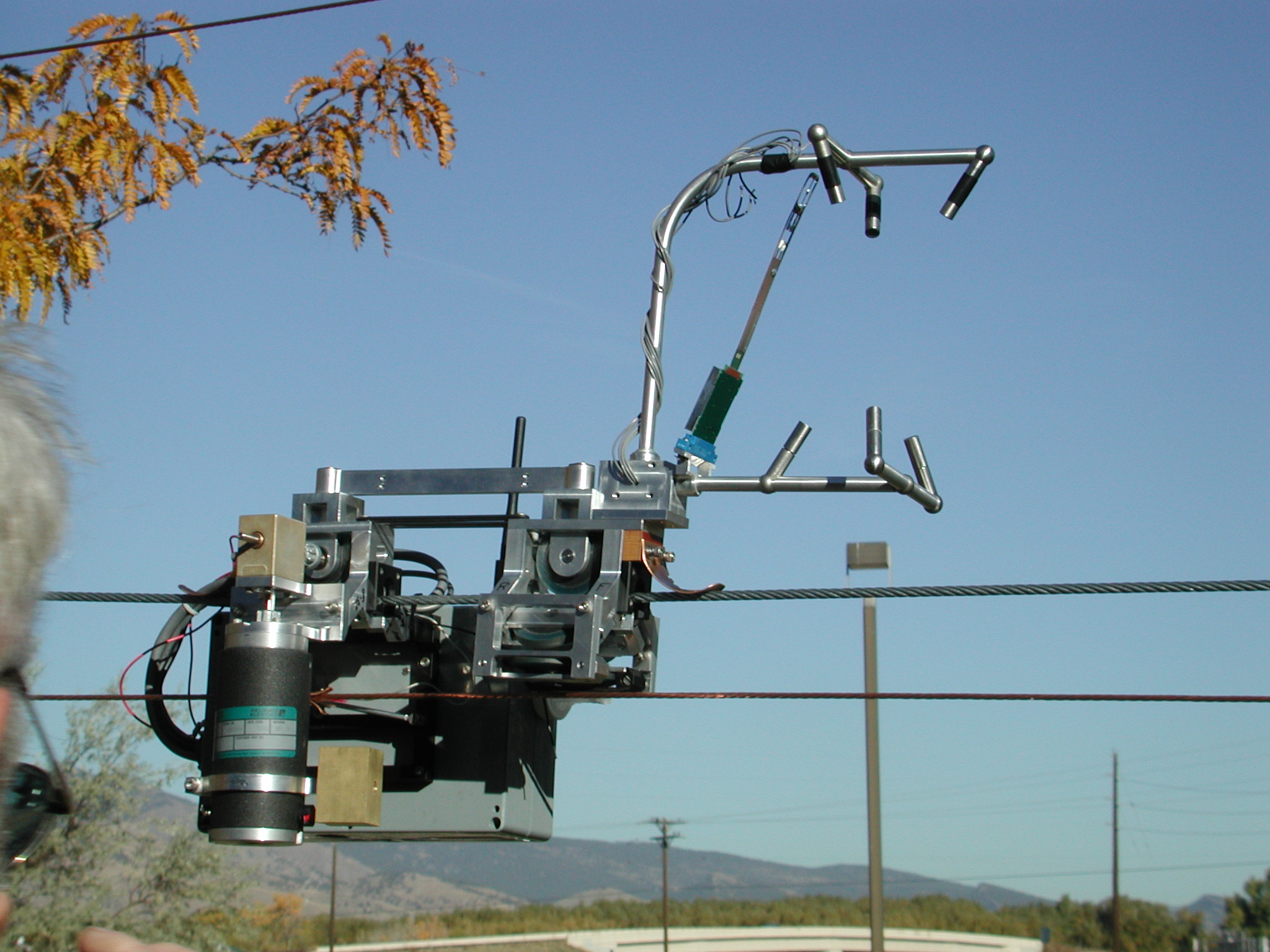
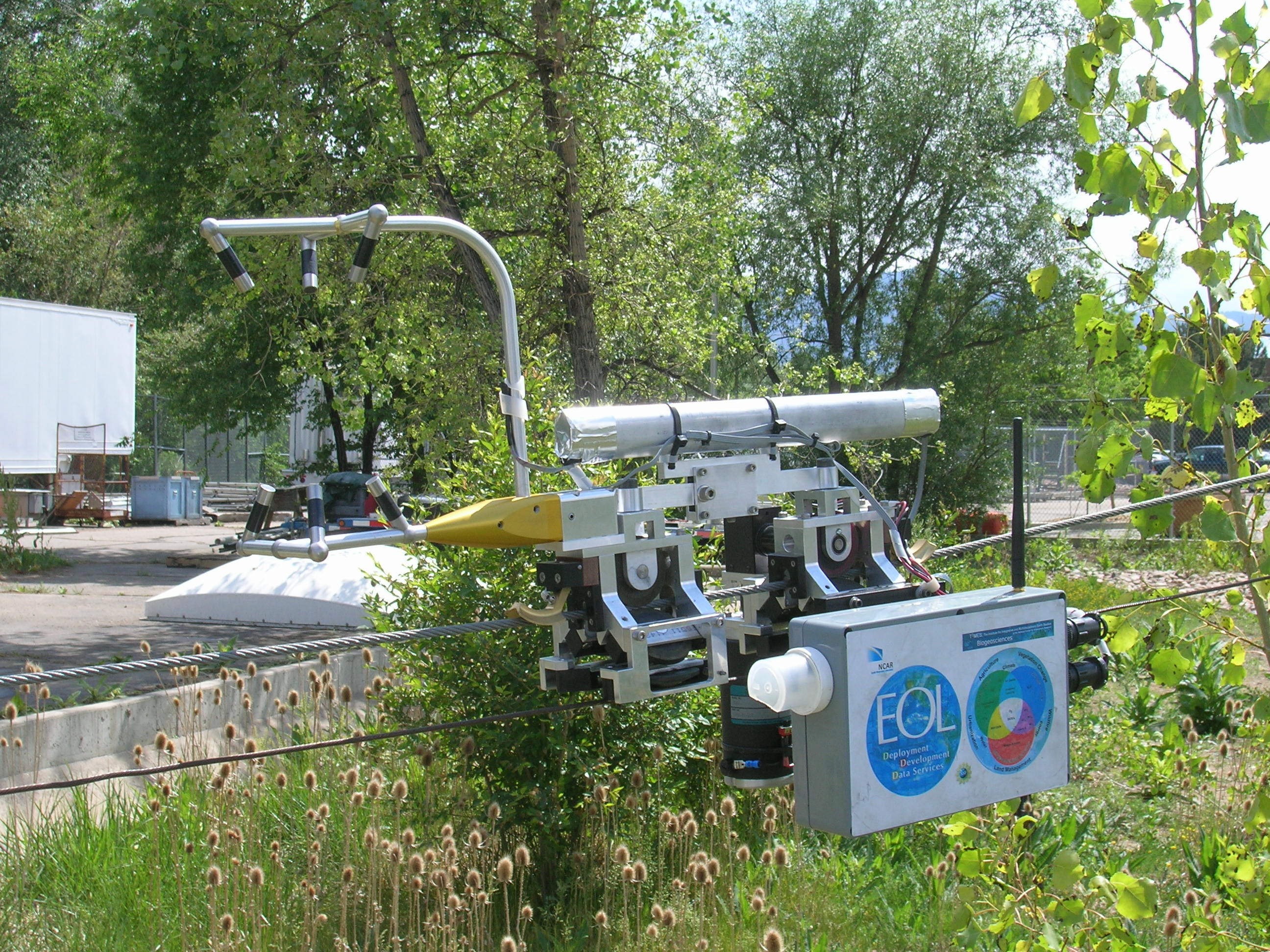
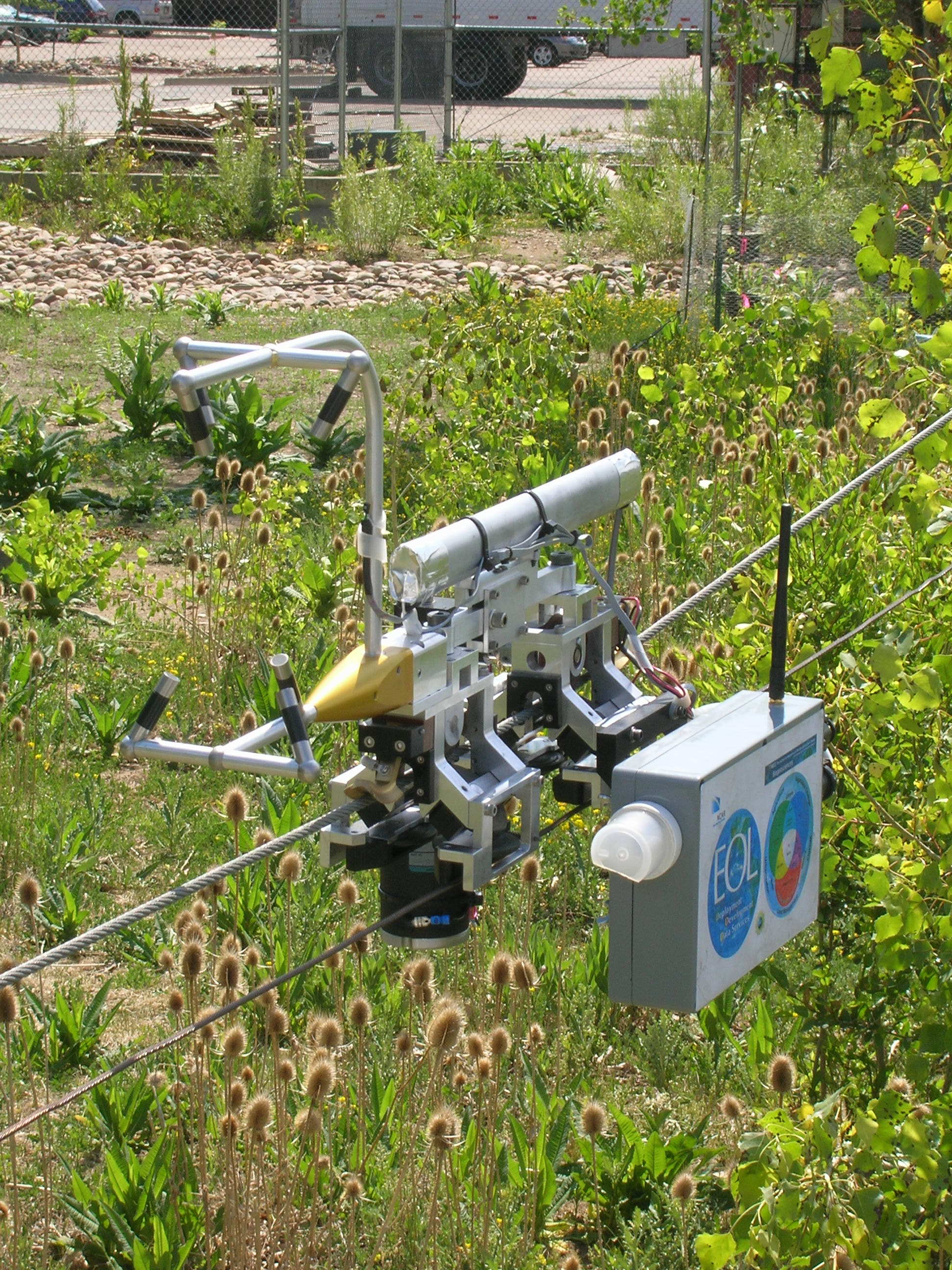
- The trolley itself. Note that some
pieces (such as the electronics for the sonic anemometer and back wheels)
are missing as the trolley was assembled for this photo opportunity.
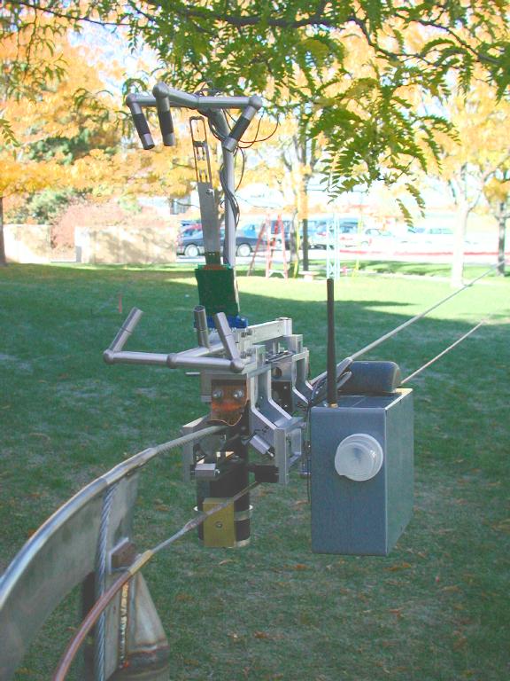
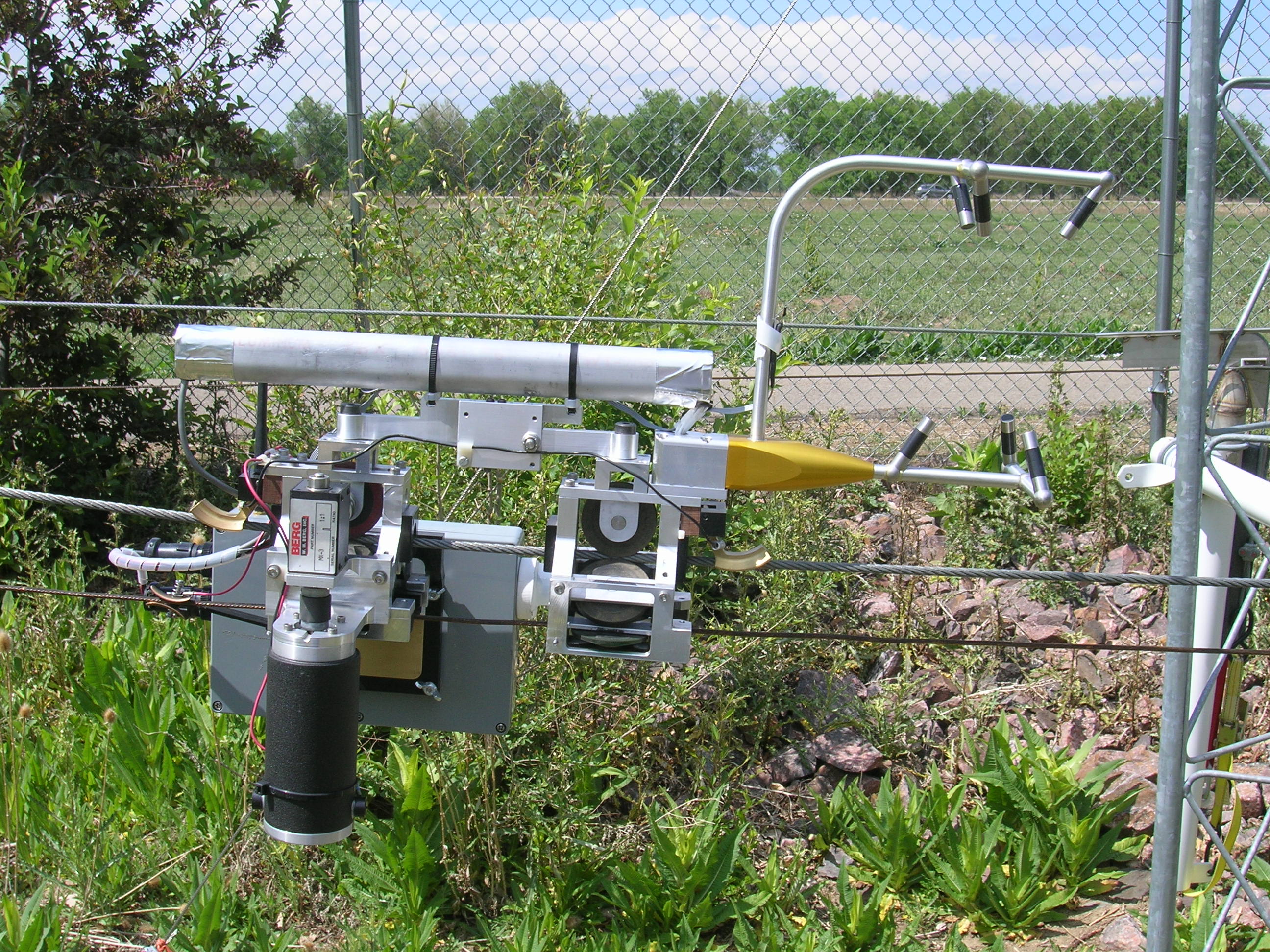
- A front view of the trolley, showing
the sonic anemometer and PTH sensor on the top and the grey box containing
the rest of the sensor package with the CO2 sensor inlet on the front panel,
and GPS receiver and antenna for data communication on the top.
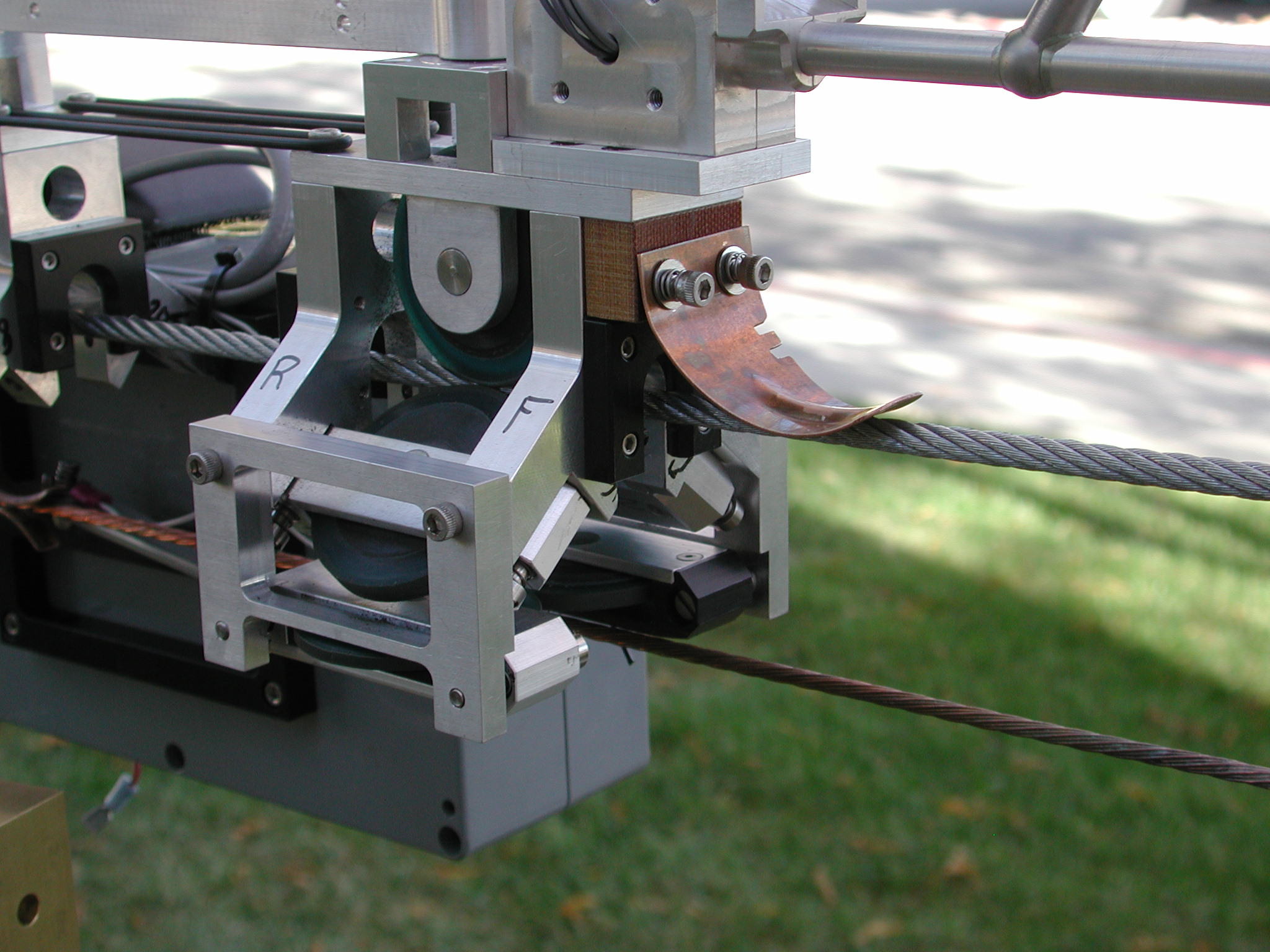
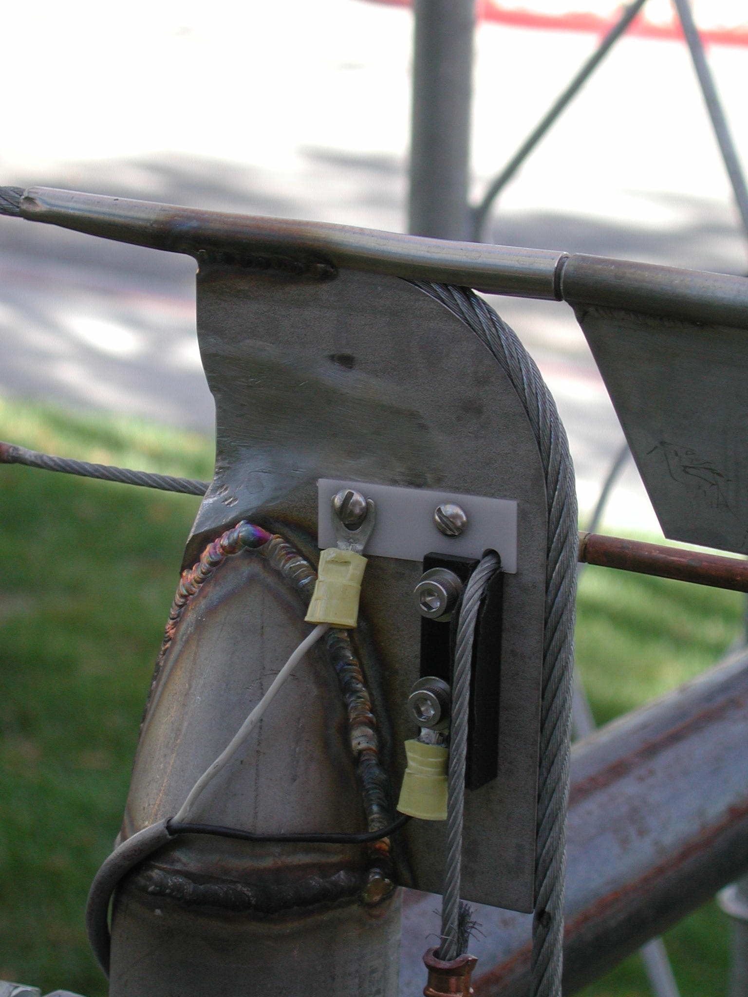
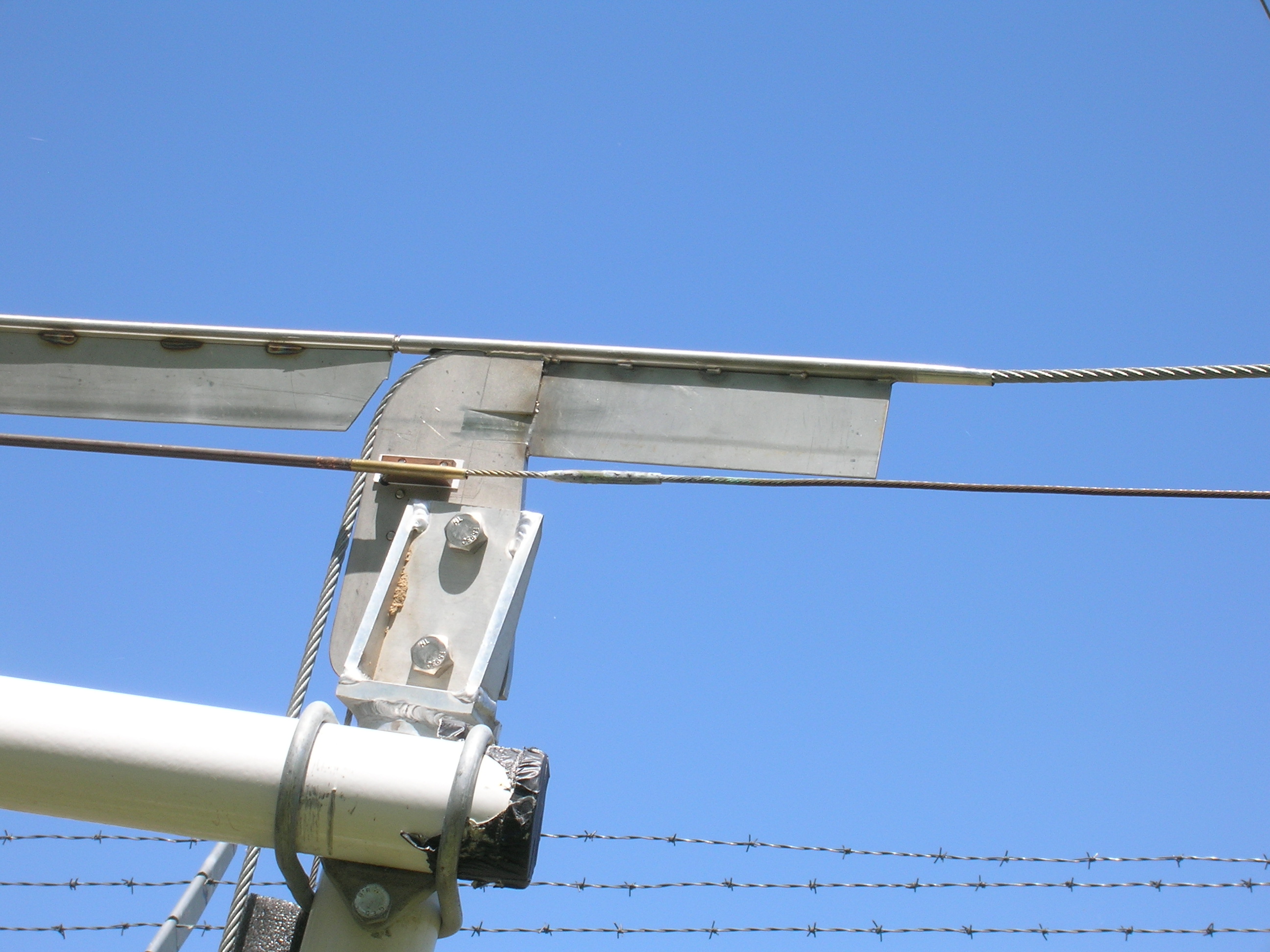
- One of the two trolley carriages which
attach the trolley to the suspension cable. Also shown is the electrical
contact to the suspension (ground) cable.
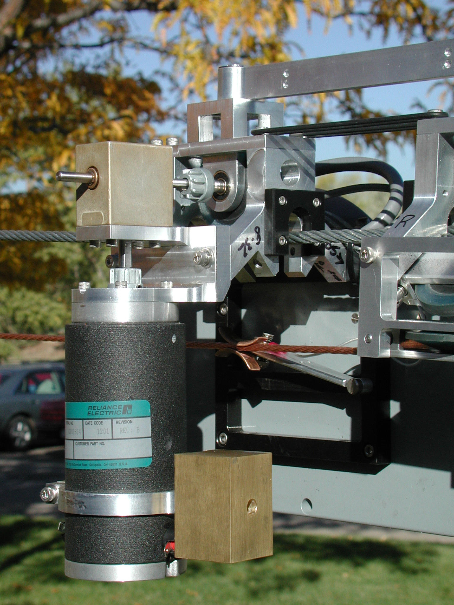
- The trolley motor and drive mechanism.
Also note the power pickup of the lower power cable.
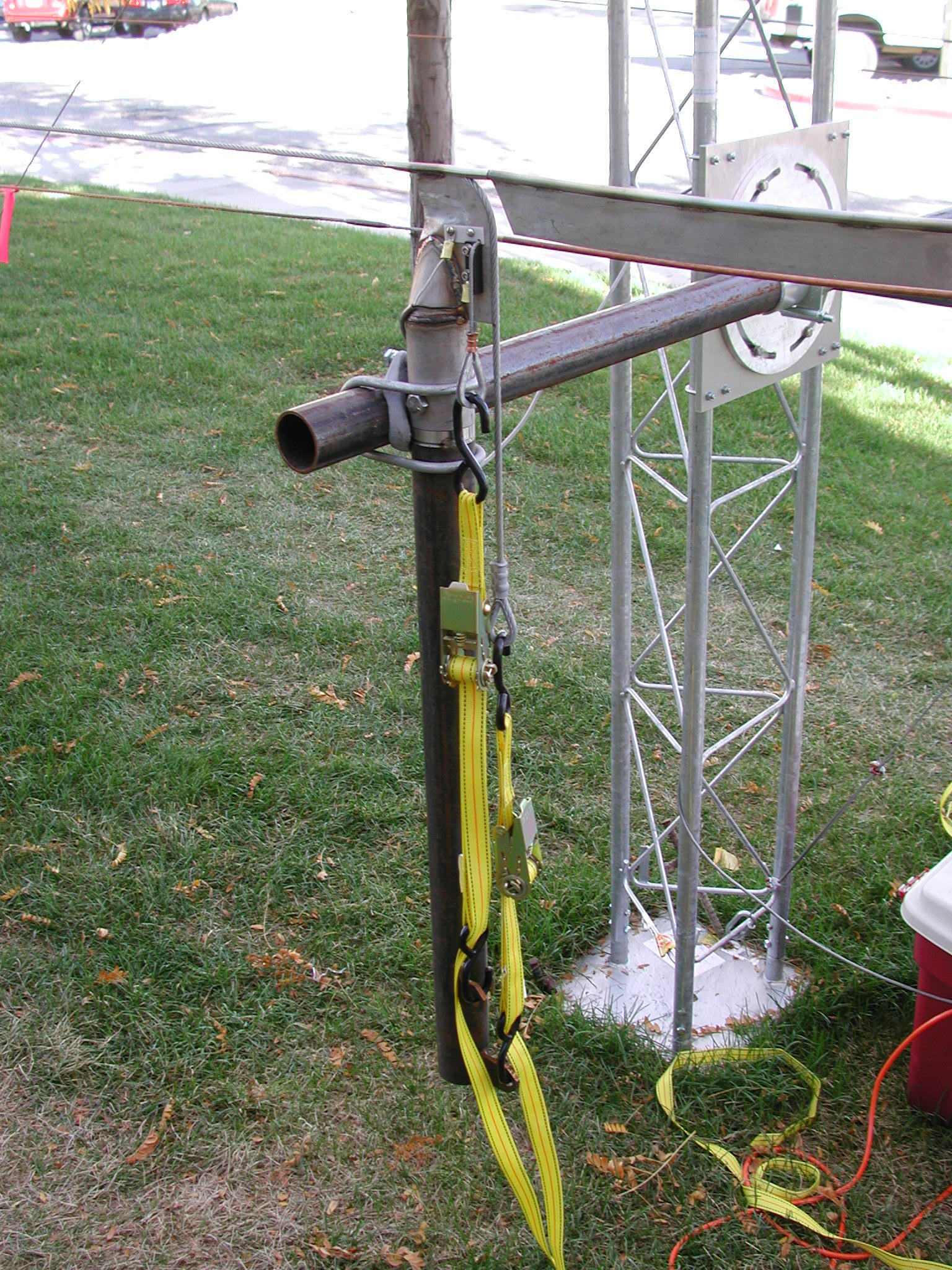
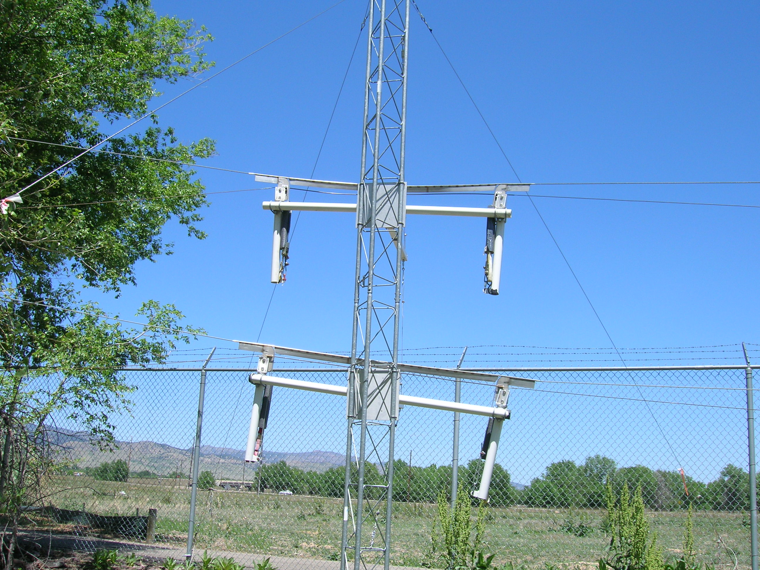
- The way the cables are powered.
- The way the cables are tensioned.
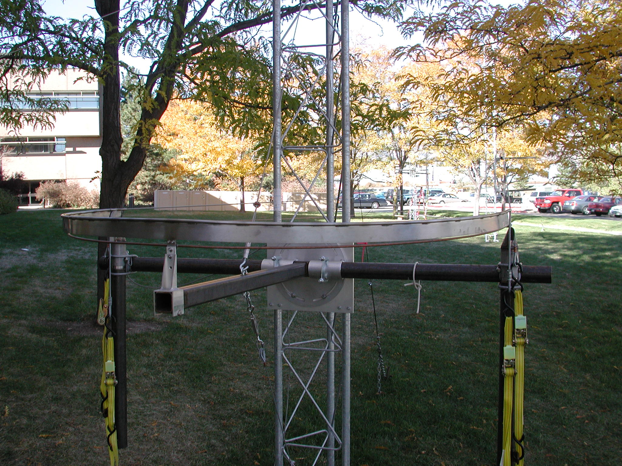
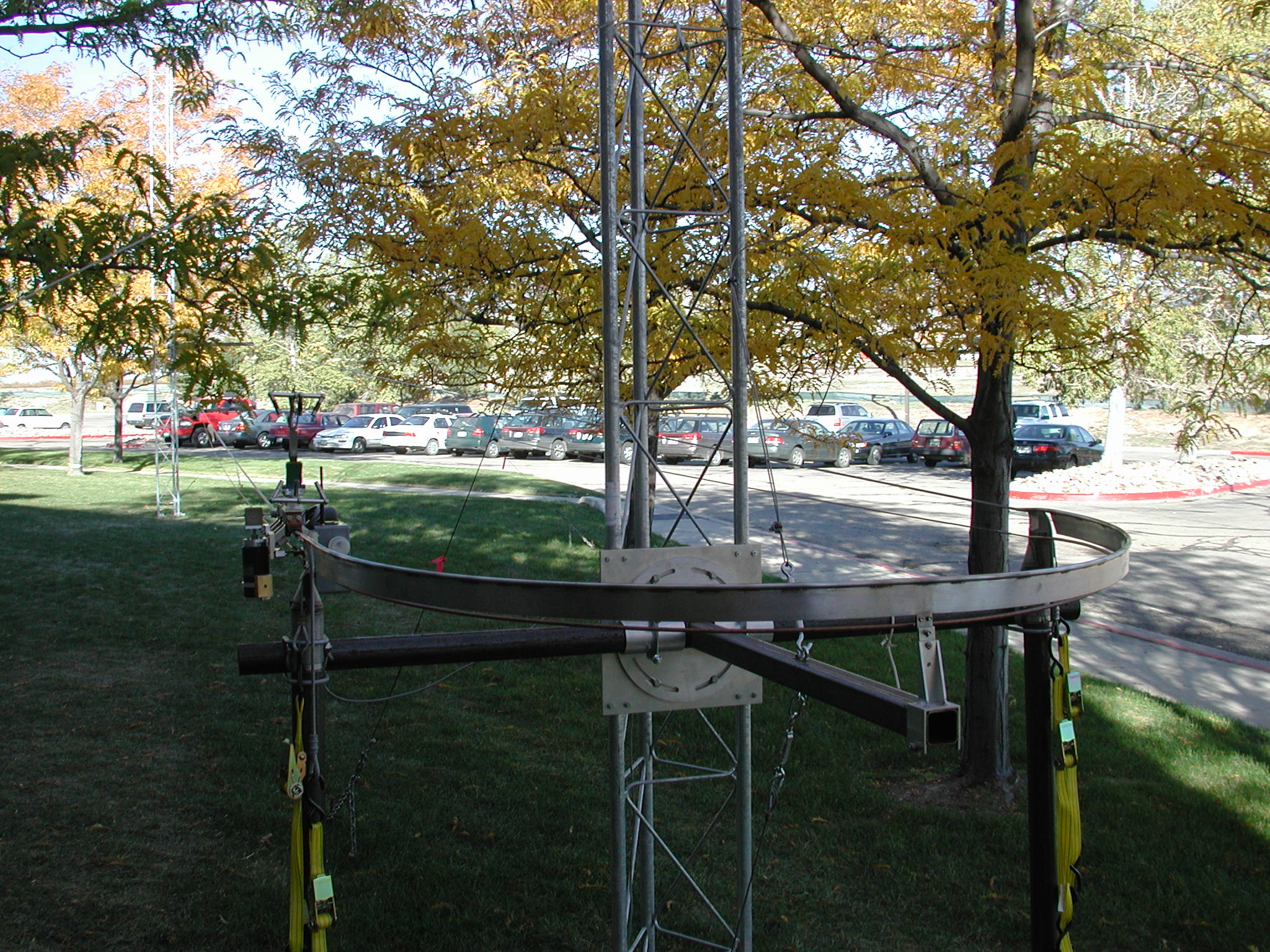
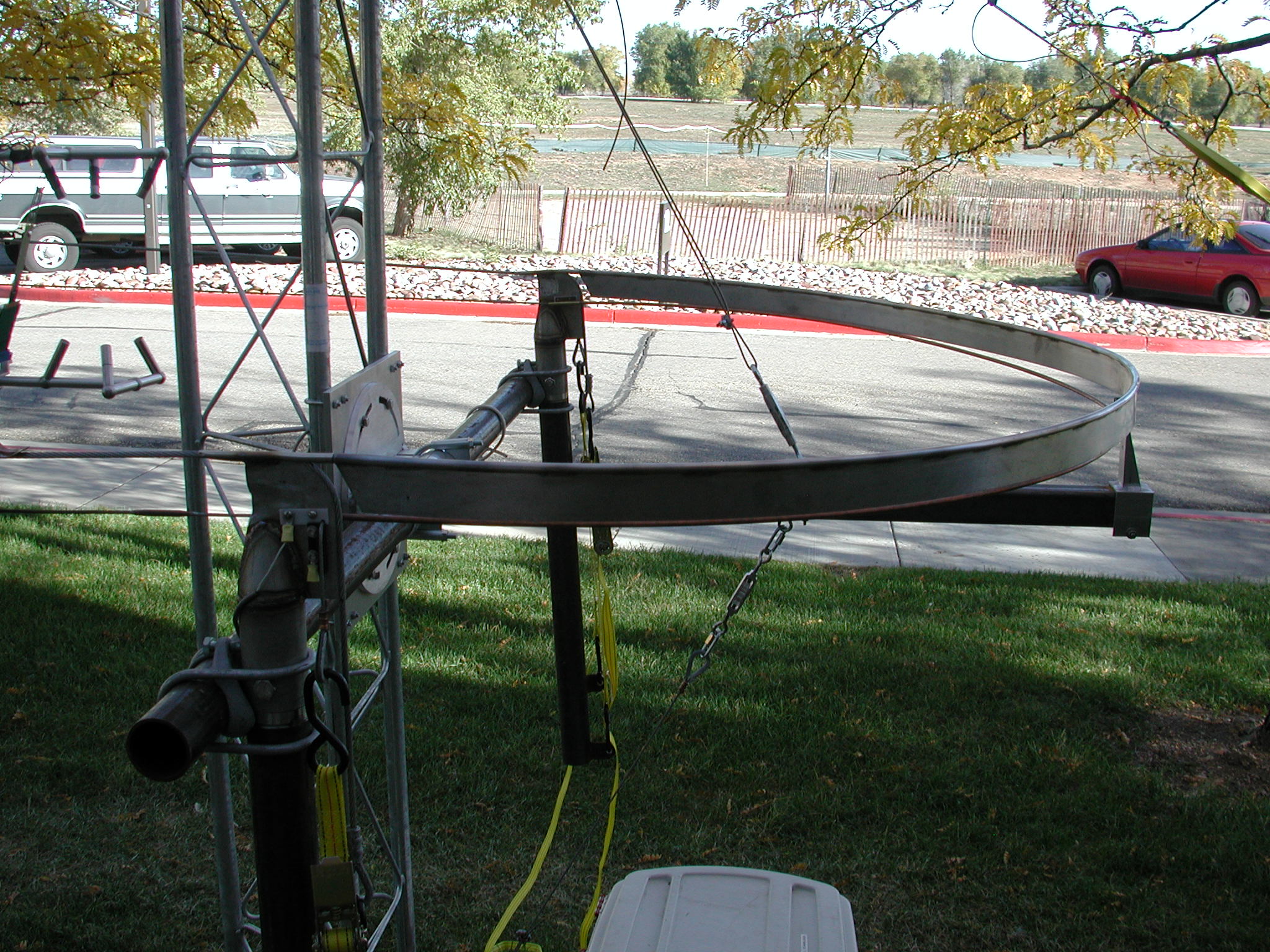
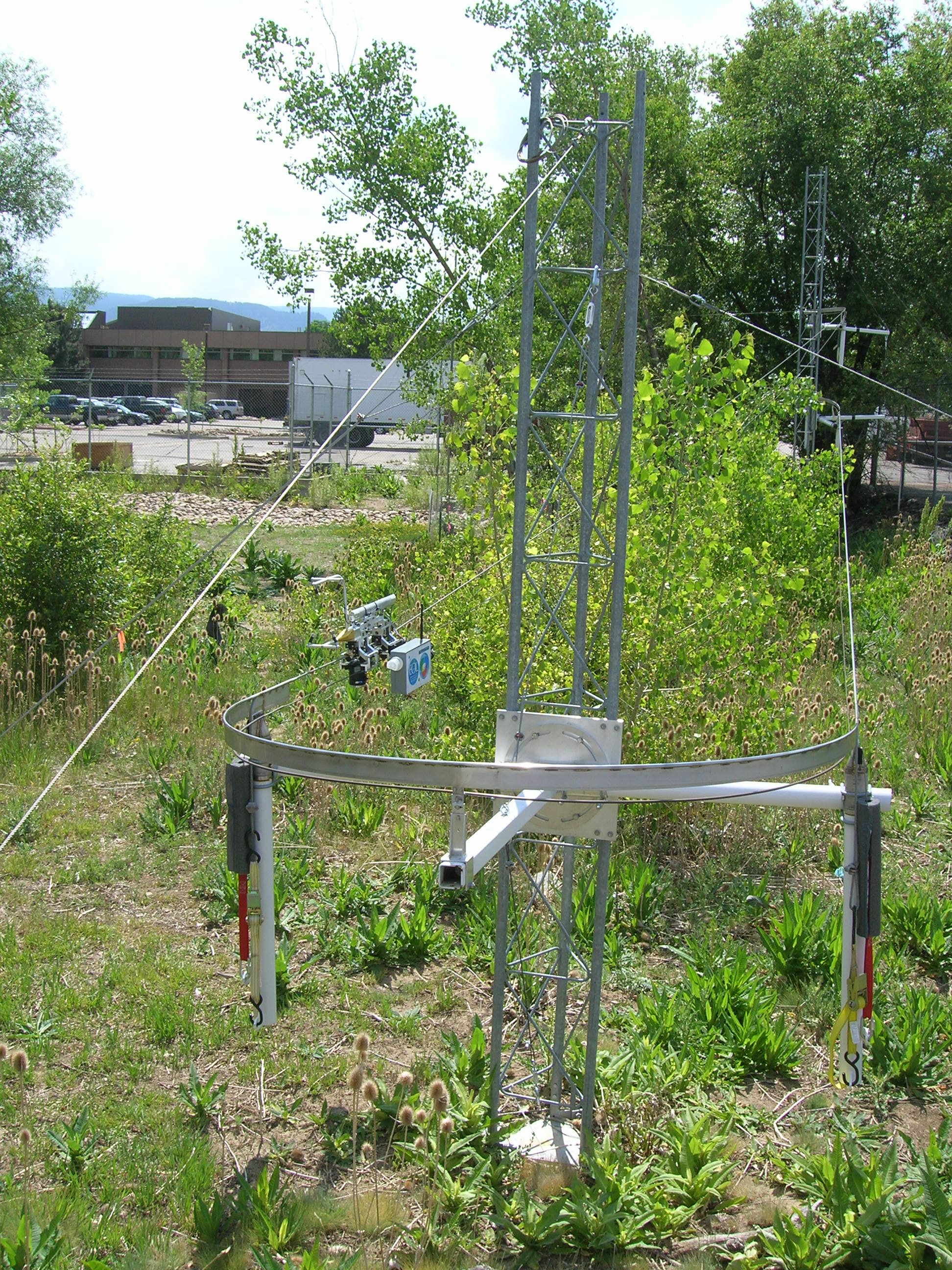
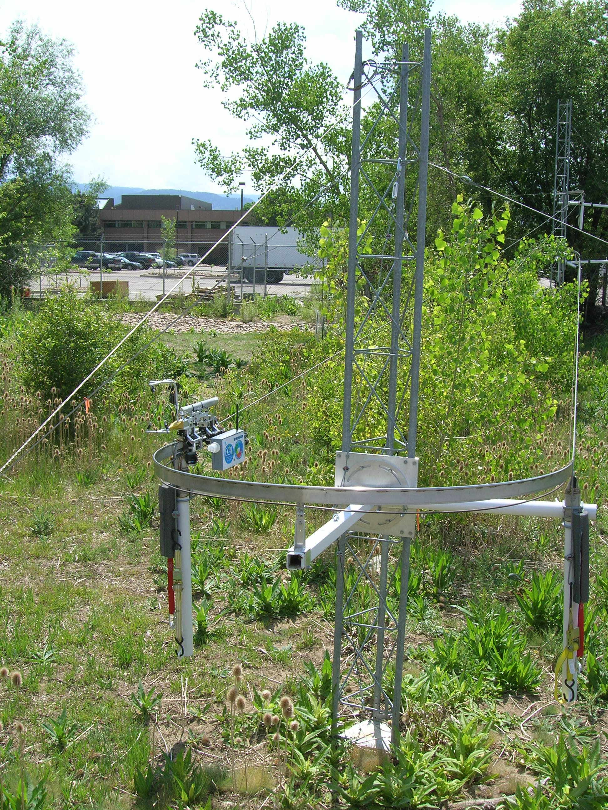
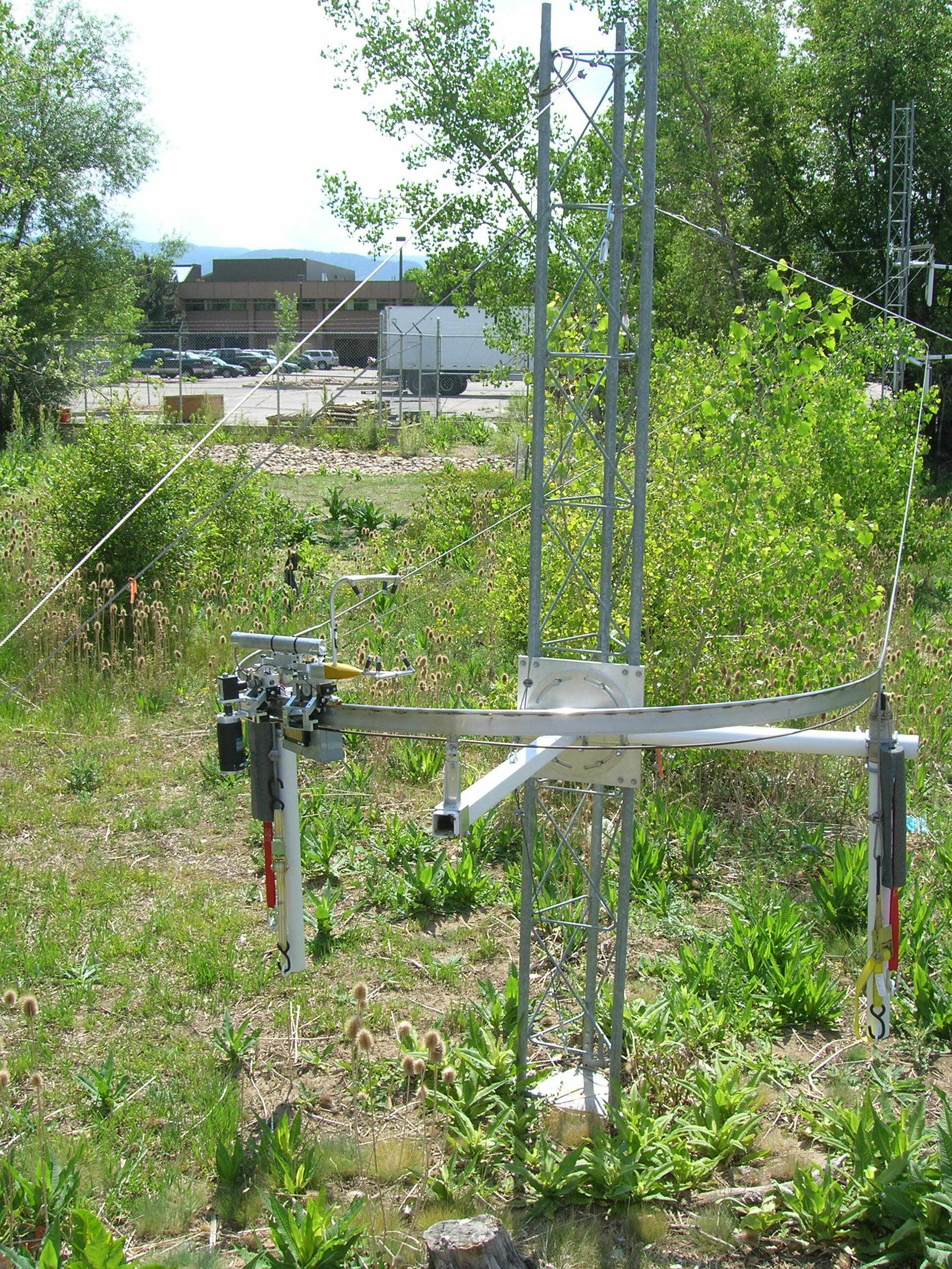
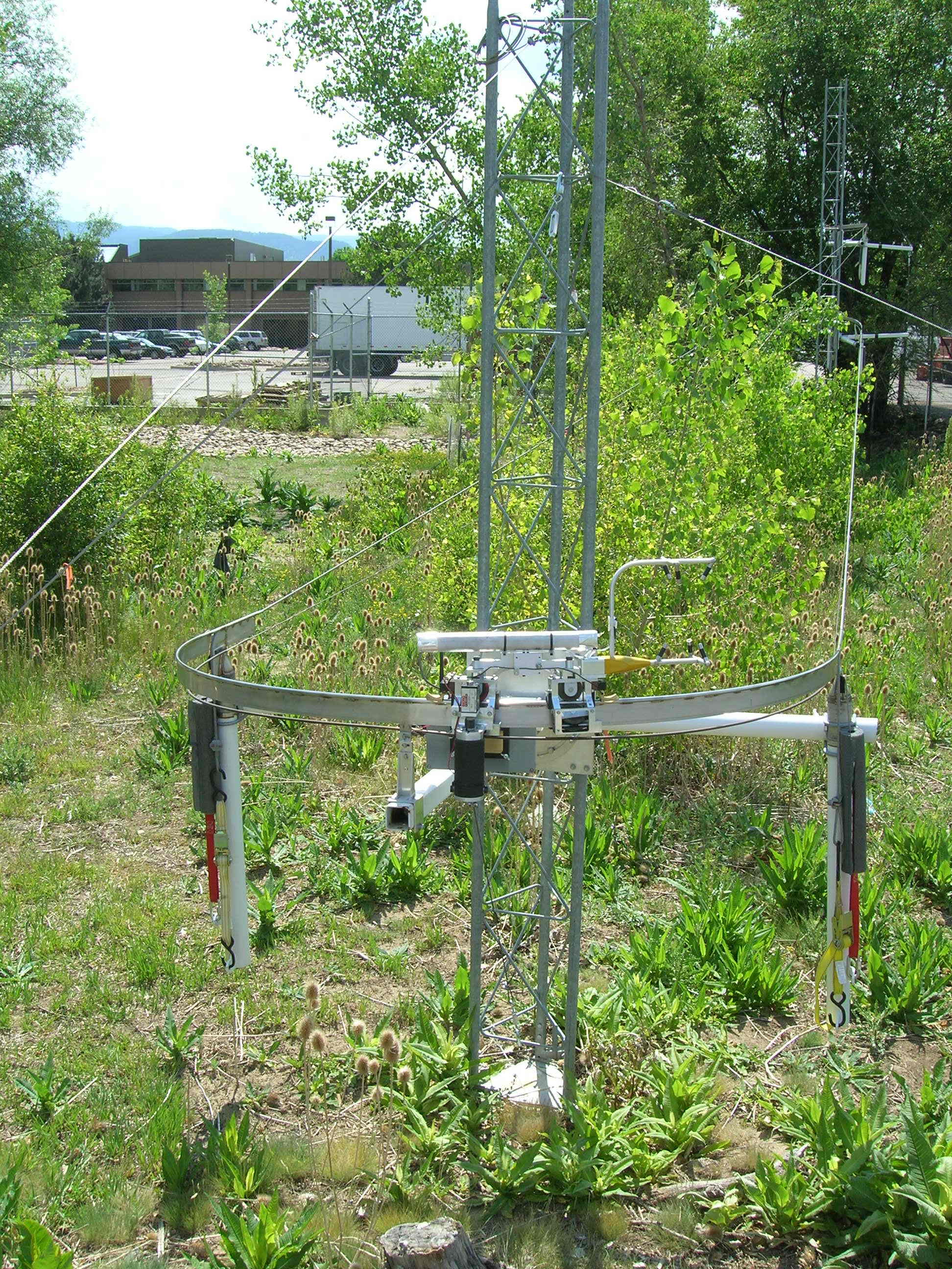
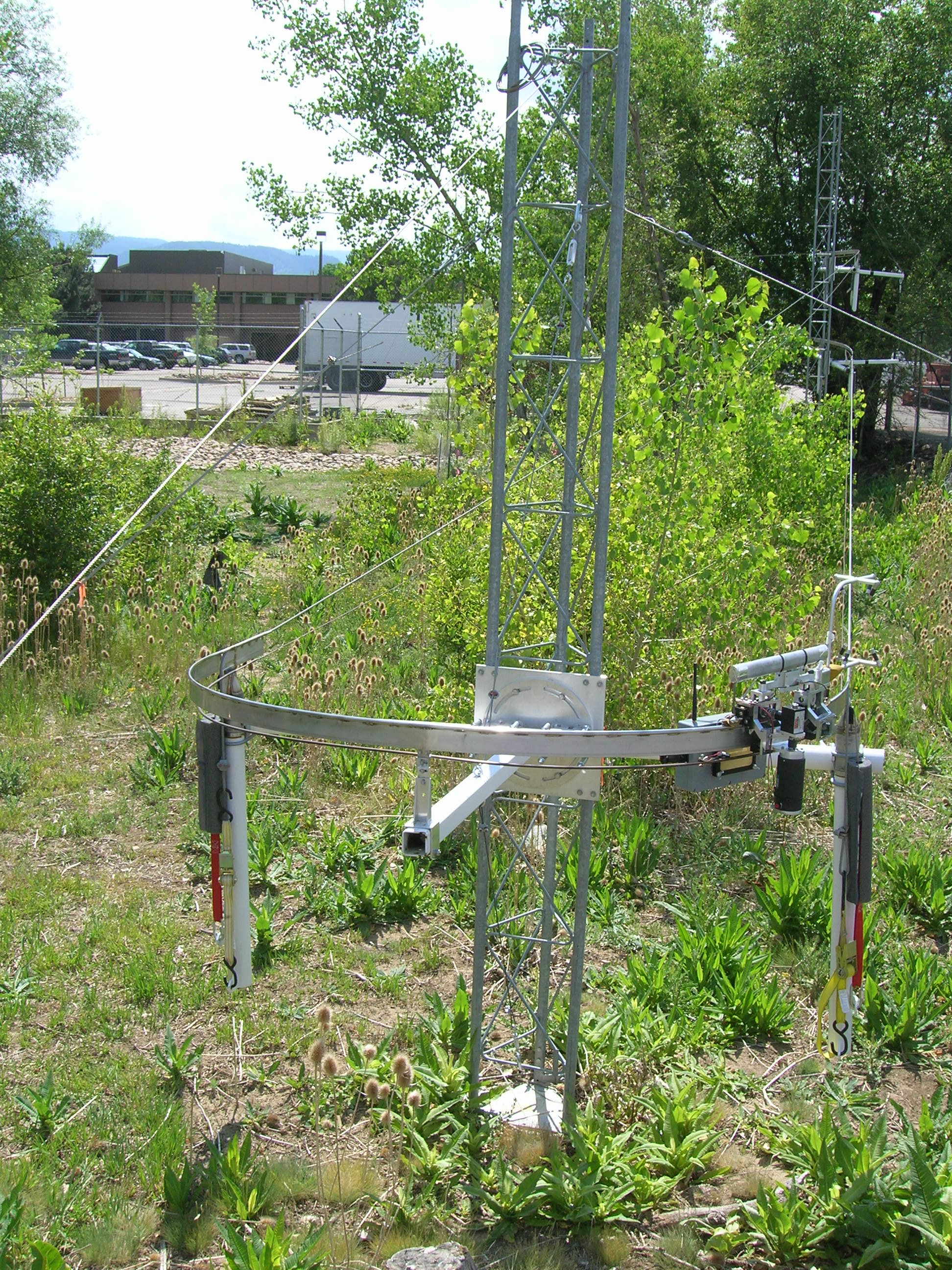
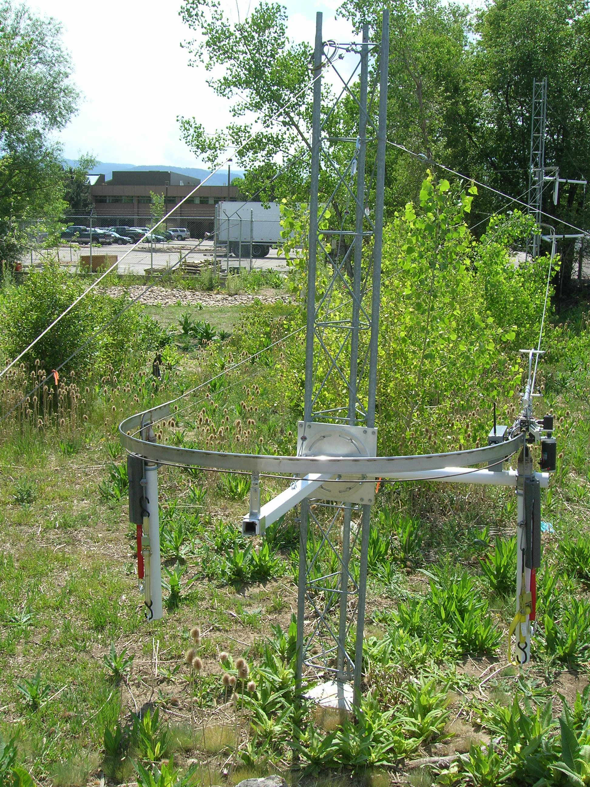
- A view of the loop from the East end.
- Another view of the loop from the East
end.
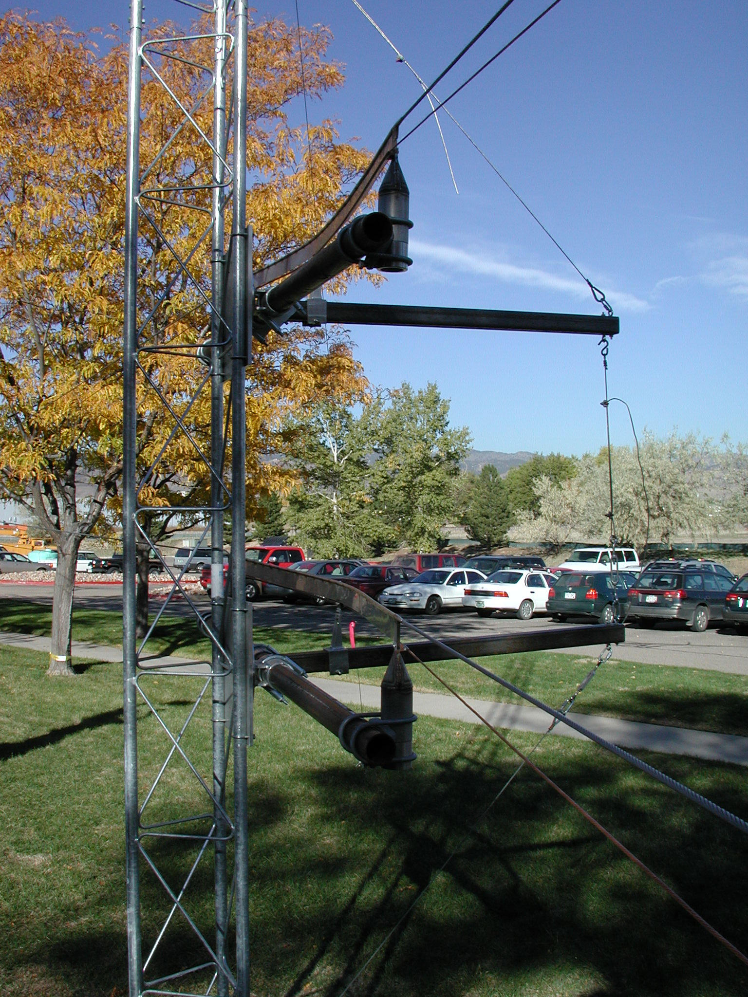
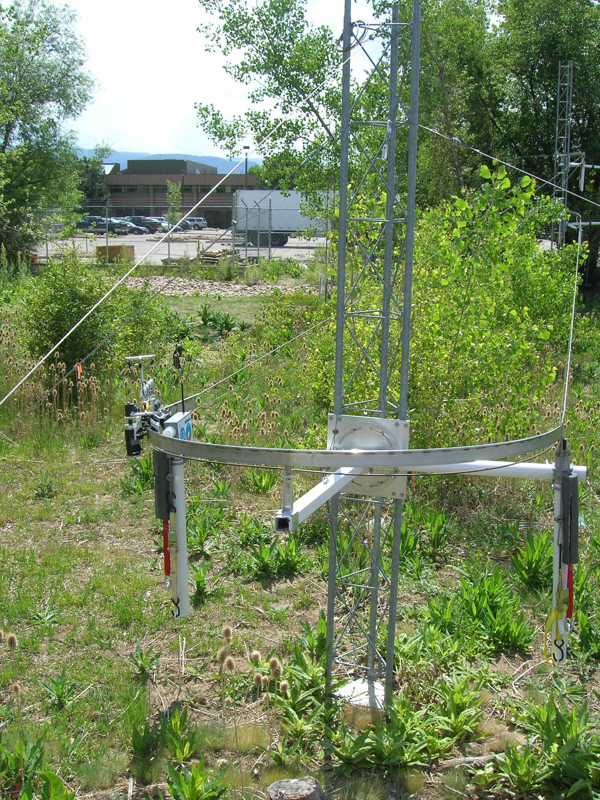
- A side view of the 180 degree turn at
the East end.
- A view of the two inner turns.
- The primary designer of this system,
Karl Schwenz.
Some video clips:
- Video at the East turn.
- Video passing the central tower (try
ignore the train in the background).
- Video at the West turn. Note the
side-to-side rocking motion upon entering this turn the second time.
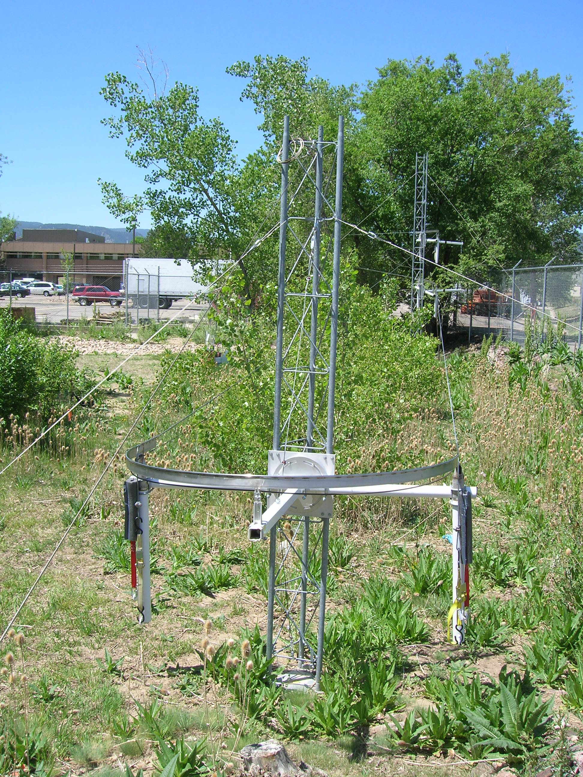
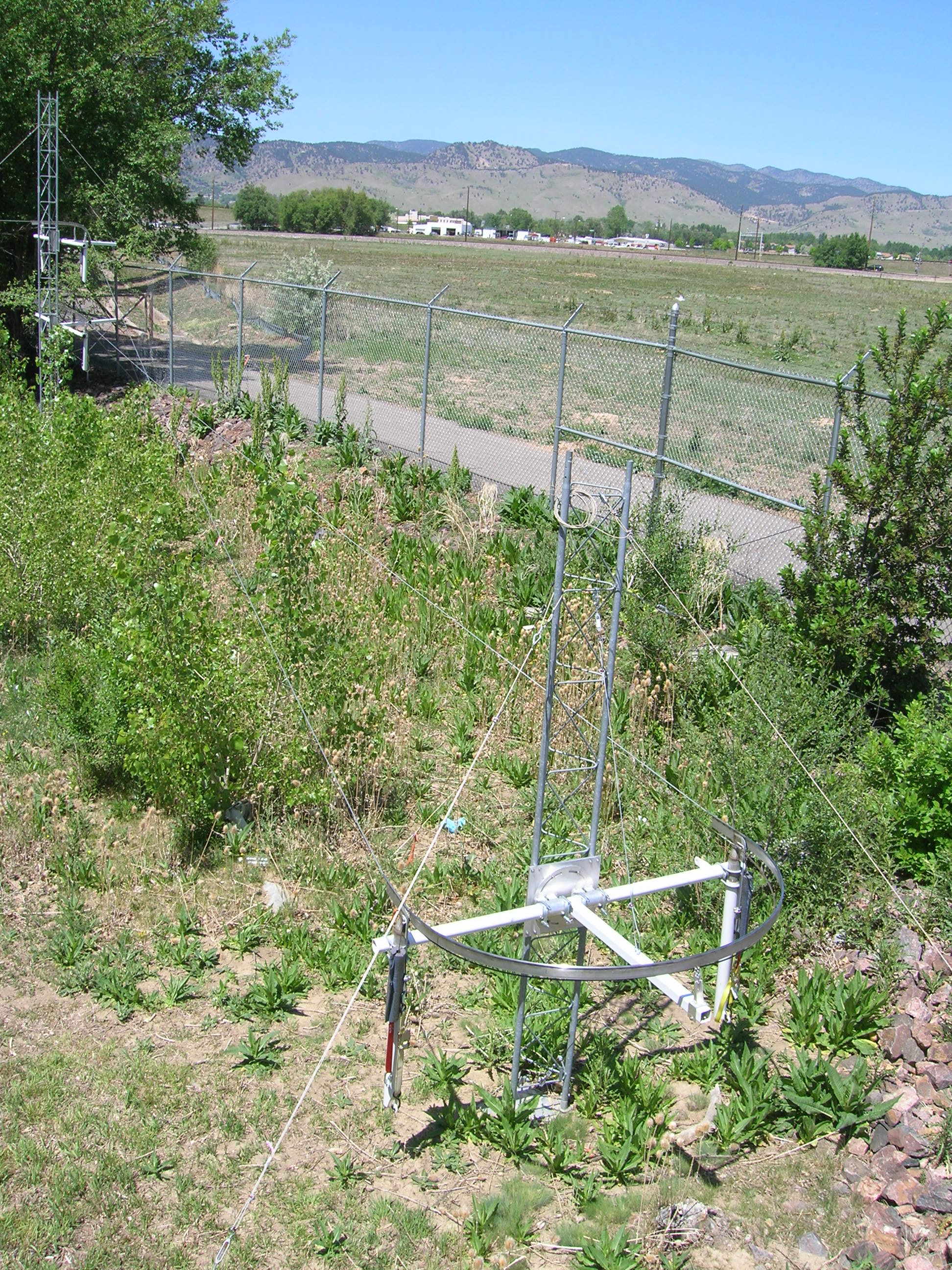
2005-present
By 2005 the 2002 circuit had been dismantled. We reerrected the test track
in the "swamp" at the far east end of the FLAB property to avoid interference
with FL0 construction and pedestrian traffic. Functionally, the new track
was identical to that in 2002, but somewhat redesigned turns were used. Most
of this reconstruction was in 2005, but trolley testing was mostly in 2006
(and will continue in 2007). We anticipate leaving this track in place for the
foreseeable future.
Some photos:
Results
During these tests, we have learned a lot about the mechanical behavior of the
trolley and cable suspension system:
- Trolley gear drive: We started in 2002 with an unsealed 1:1 90-degree gear
box. It quickly burned up. We changed to a sealed 1:1 gear box which lasted
until replaced in 2006. We now use a 2:1 gear box which gives the trolley
more torque to carry it through turns and better "engine" braking. This was
perhaps the most significant increment we made in increasing TRAM reliability.
With this change, we are now operating at 42 VDC rather than 28 VDC. Even
though this is less than a doubling of voltage, the average TRAM speed is still
about 4 m/s, due to the now increased speed through turns.
- Turns: Before changing to the 2:1 gear box, the trolley would need to be
operated at high power to get it through turns, with the disadvantage of having
it run at high speed along the cable coming into turns. Any rocking motion
developed during the cable run could cause physical jarring when the trolley
entered the turn. Adjusting nose orientation (both in azimuth and pitch now
possible with the 2006 noses) is critical. Extending the "flat" to the nose
(2006 noses) also helps to dampen the rocking developed upon exiting the turn
and to more smoothly align the trolley when entering the turn.
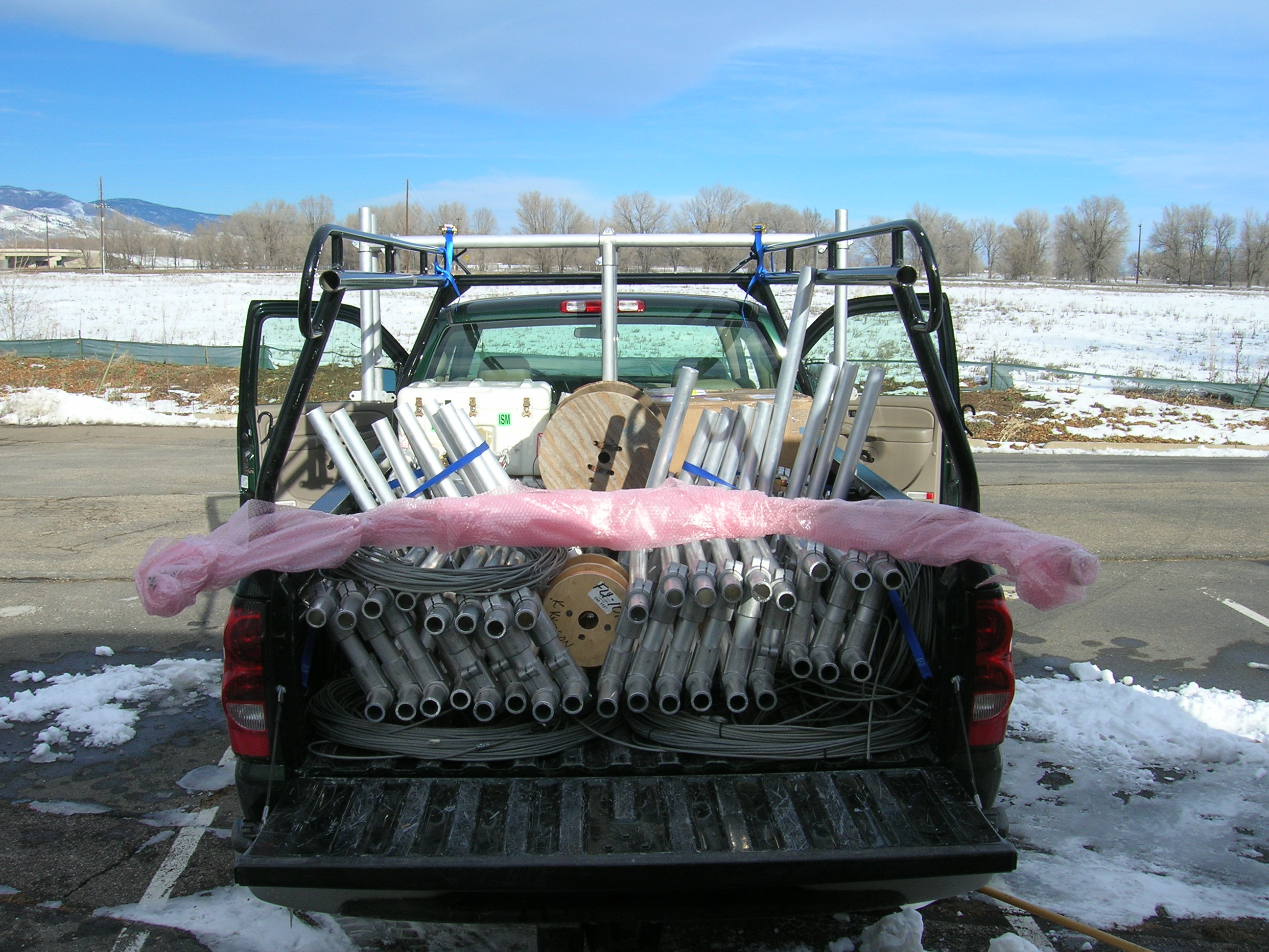
- Turn support: For Niwot07, a totally new set of turns was constructed,
based on aluminum (rather than steel) tubing and standard pipe clamps.
These are somewhat lighter and should be easier to adjust.
- Cable: Tensioning the suspension cable to "just" tight seems best. We leave
the power cable slightly loose in part because the trolley sags in the middle
of the run and also to give the trolley a bit of braking through the power
pickup.
- Power pickups: In mid 2006, we changed from slider to roller pickups on
the suspension (ground) cable.
This should reduce wear on these parts (and associated accumulation of brass
rubbings on the wheels) and also reduce the possibility of sparks.
There also were several sensor/data system changes from 2002 to 2006:
- Sonic anemometer: In mid 2002, the array was downsized from 20cm to 15cm
paths and changed from stainless steel to aluminum tubing to reduce stress
on the array during turns. No other major changes have been made. This sensor
does require some wind tunnel testing for flow distortion around the array
and trolley.
- CO2: TRAM settled on the RMT
DX6100 CO2 (only) IRGA due to size and
weight and has not changed (though we have been informed that this model will
soon be unavailable). This sensor is somewhat noisy ~10ppmV at 10sps, but
we plan to be looking for large CO2 gradients and probably can tolerate some
amount of averaging. We haven't tested the long-term accuracy, but plan
on operating a stable sensor at a fixed location on the TRAM circuit for
continuous, in-situ comparisons. Air is brought in to this closed-path sensor
using a small KNF NMP05 microdiaphragm pump.
- T/RH: In 2002, TRAM used a Vaisala PTH sensor from a radiosonde (as TAOS
used). In 2006, we changed to an
SHT75 solid-state T/RH sensor which should
have better long-term calibration stability and better accuracy.
- Attitude: In 2002, TRAM (like TAOS) used a single-axis flux-gate compass
(TCM2).
combined with a fluid-based attitude sensor. This suffered from
inertial effects, especially in turns. In 2006, we changed to a Honeywell
3-axis compass (HMR3300).
- GPS: In 2002, TRAM used a Garmin
GPS-35
hockey-puck receiver. In 2006 we
changed to a lower-power Trimble
Lassen iQ
OEM postage-stamp sized unit, with an ultra-compact antenna. Both receivers
have the ability to utilize differential GPS corrections (RTCM) on a second
serial port, but this capability has not been implemented (because we do not
yet have a DGPS base station). We also now have a battery backup to allow
GPS "warm starts" (typically 20-60 s).
- Bar Code: GPS data at ~10m accuracy are not adequate for locating TRAM
position. In 2006, we added a crude bar-code system based on
OPB716 sensors
to report a
unique serial number as the trolley passes each tower (known reference points).
This system never worked properly in field conditions, due to skewed alignment
of the sensors in the middle of turns (solvable), out-of-sync codes due to
gaps in the track (solvable), and erratic response to lighting conditions
(not solvable). We thus changed to an RFID system [see next].
- RFID: This system uses commercial components from Intersoft.
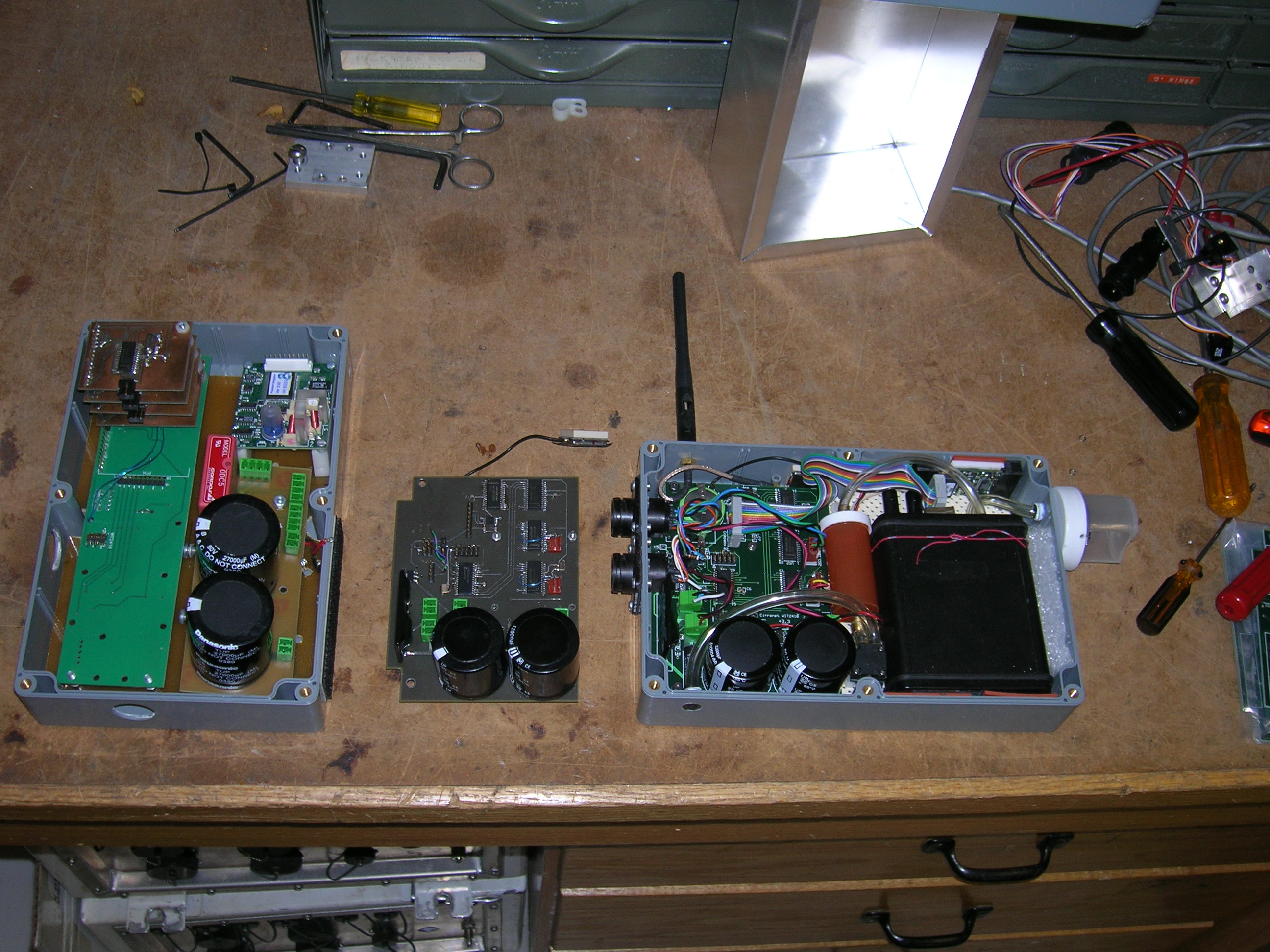
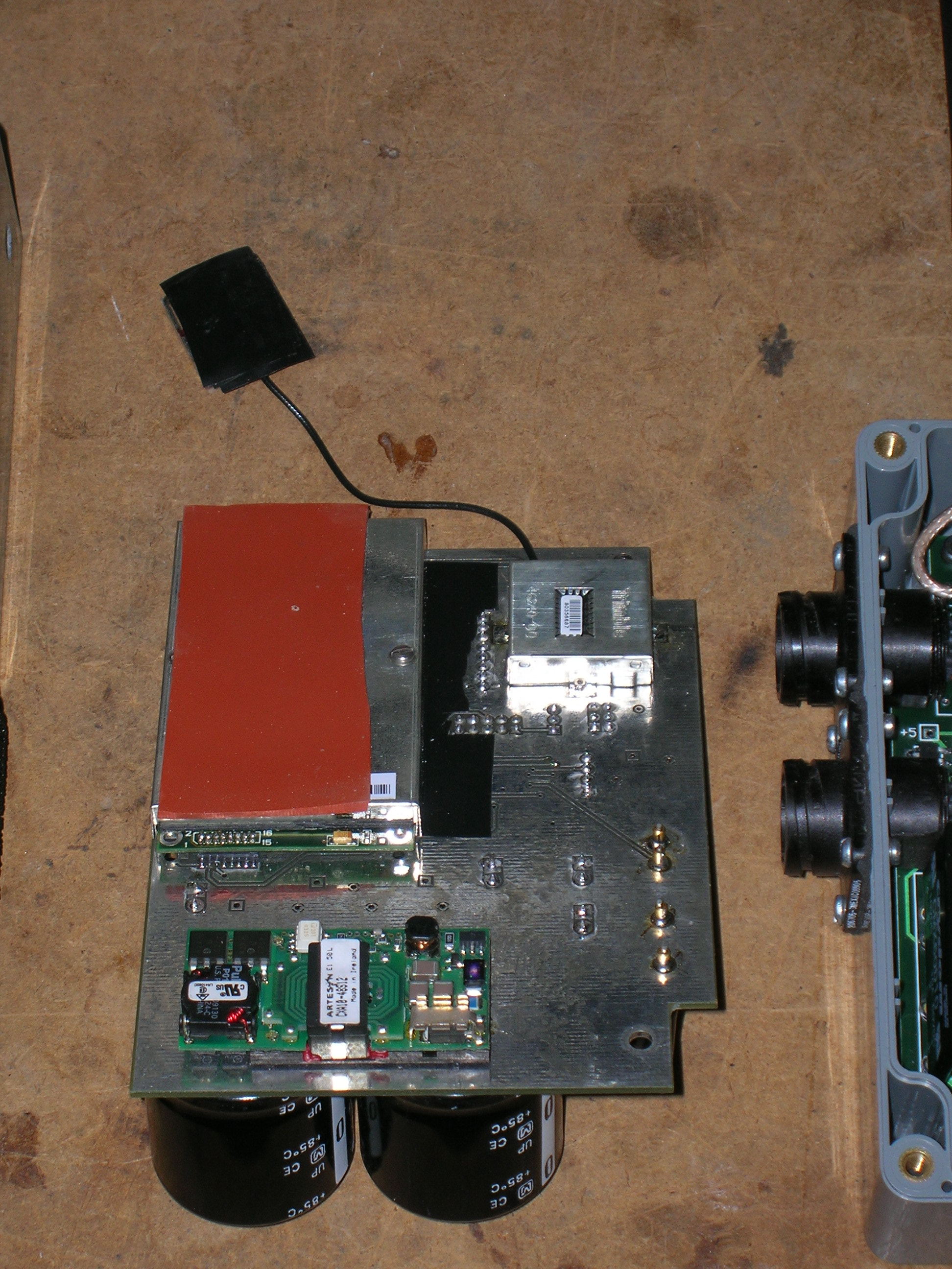
- Data system: TRAM has always used a PIC 18F252 running embedded C code
with auxillary serial ports or on-chip I/O lines to communicate with sensors.
In 2002, this was based on the TAOS CPU board. In 2006, a new board layout
was made just for TRAM. The new board has on-board power monitoring and
an analog input to be used for a PAR sensor (not yet implemented). It also
has an expansion connector which may be used to connect to a wireless
sensor network. [In this photo, the 2002
version data system is in the box to the left (uncabled) and the 2006 version
is in the box to the right (with the black CO2 sensor). In the middle is
the prototype version of the 2006 data system -- the
backside is where the radio and GPS are
mounted.]
In 2006, the software was ported to a new compiler with fewer
restrictions (and bugs!).
- RF communications: The trolley communicates to the base via Cirronet
WIT2410 2.4 GHz RF modems, as did TAOS.
This system is capable of asynchonous communication
to more than one trolley, though testing in 2002 failed to make this work.
ISFF is now using MaxStream radios that have an easier method to implement
this capability, but TRAM has not yet needed to change.
- Power control: The TRAM data system always had a solid-state relay to
allow the trolley motor to be turned off via remote control. It is intended
to use this in the future both to avoid crashes between multiple trollies
operating on the same circuit and to turn off the trolley during rain, since
water causes the drive wheel to slip and wear down rapidly. In 2006, the
relay was changed to one capable of higher-voltage operation (needed when
using the 2:1 gear box). Also, the software was changed to not turn on the
motor until the GPS had signal lock.
- Box: With all the changes from 2002 to 2006, the data system was able
to fit in a somewhat thinner box, which should reduce flow distortion.
- Power supply: TRAM has used old linear power supplies since it
requires relatively high voltage (30-40V) and current (10A). A Lambda
GEN 60-25 supply
(WWW page,
manual) was obtained in late 2006
which is much lighter(!) and has an RS232
input for control. This could allow us to change trolley speed as a function
of time of day or position along track. The supply also has a master/slave
mode which could allow multiple supplies to be used if the TRAM circuit was
quite large (and suffered from power drop).
With all of these changes, we are reasonably confident that we (finally) have
a system capable of operational use.
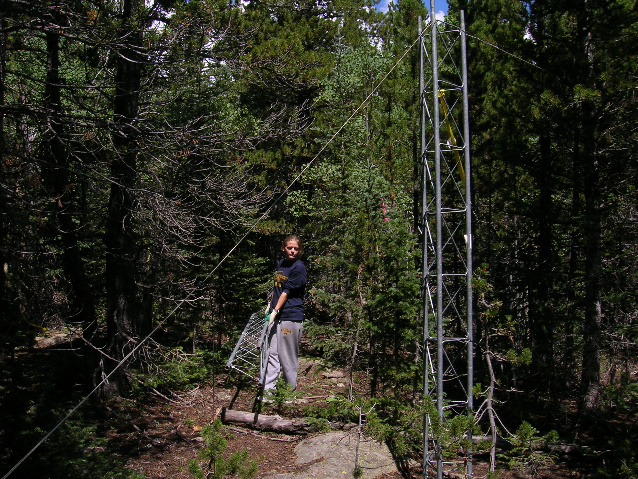
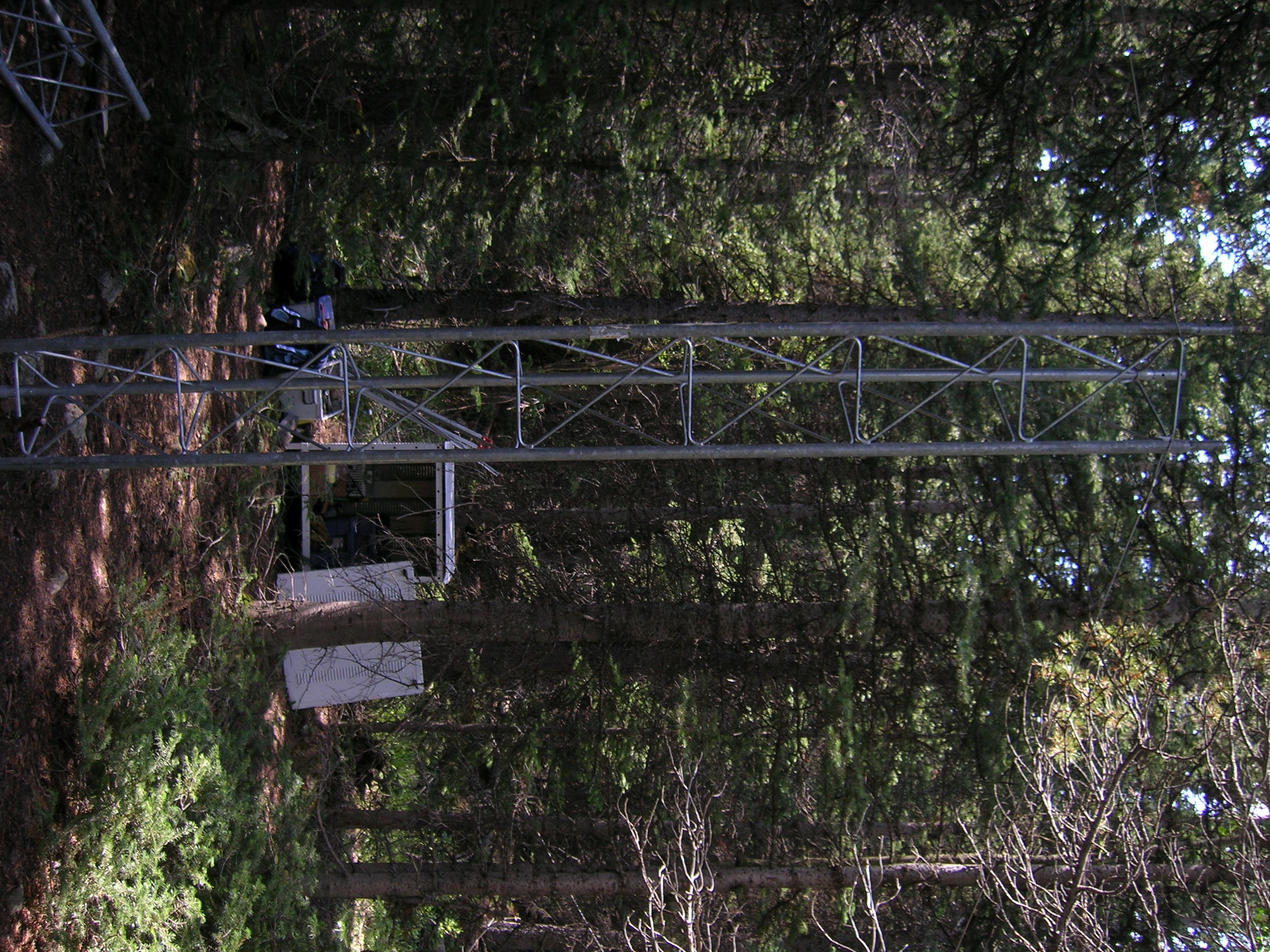
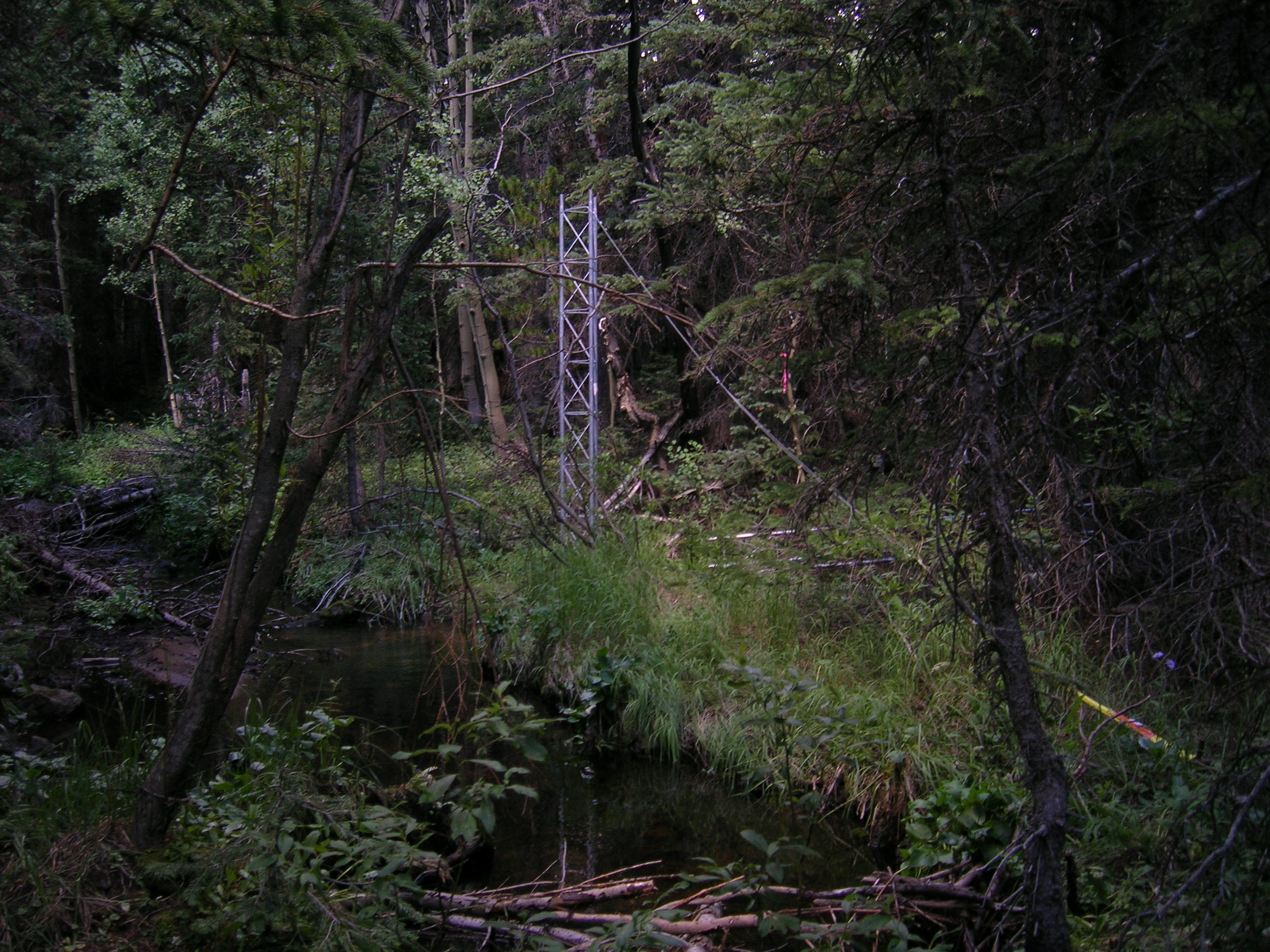
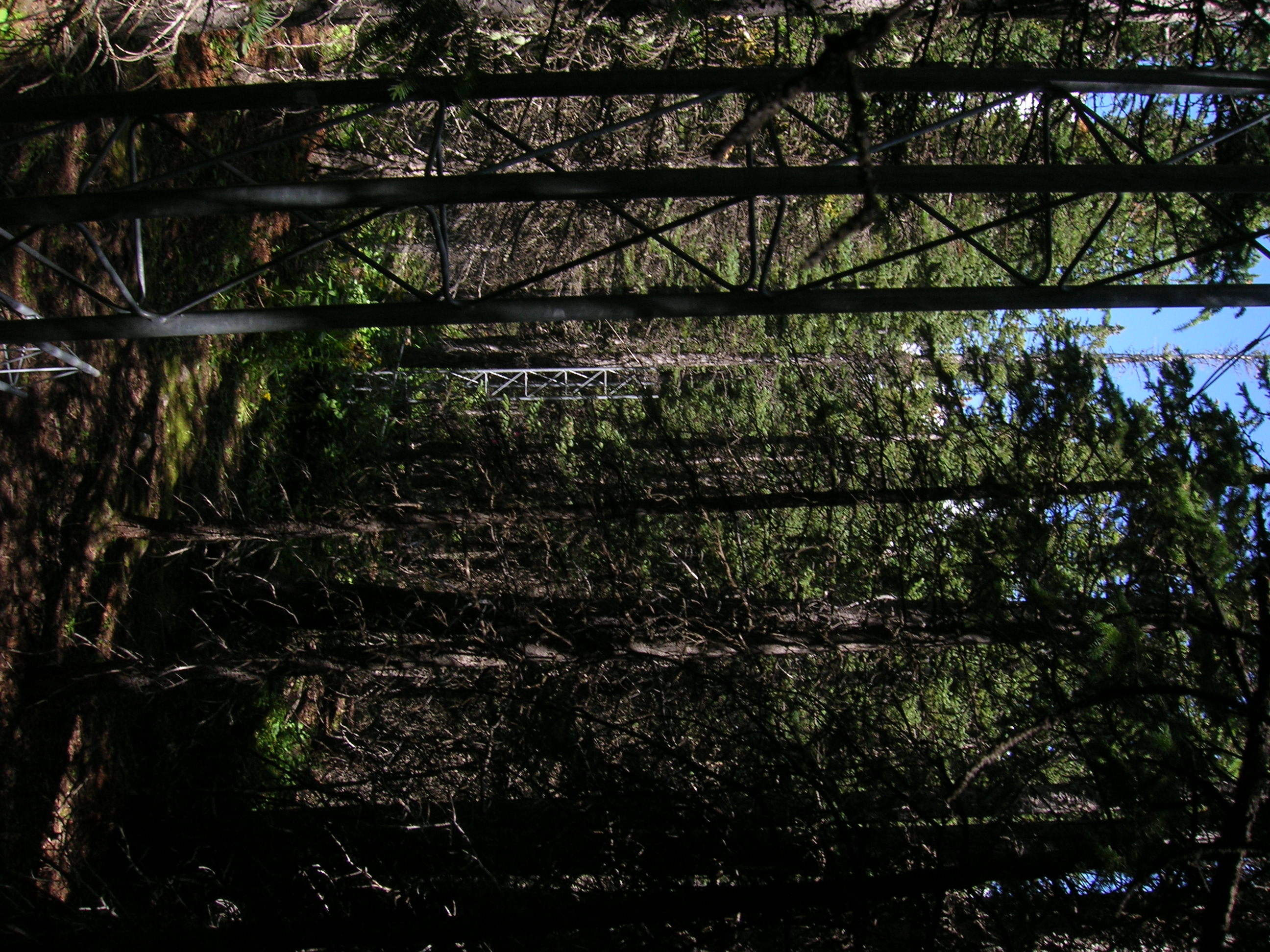
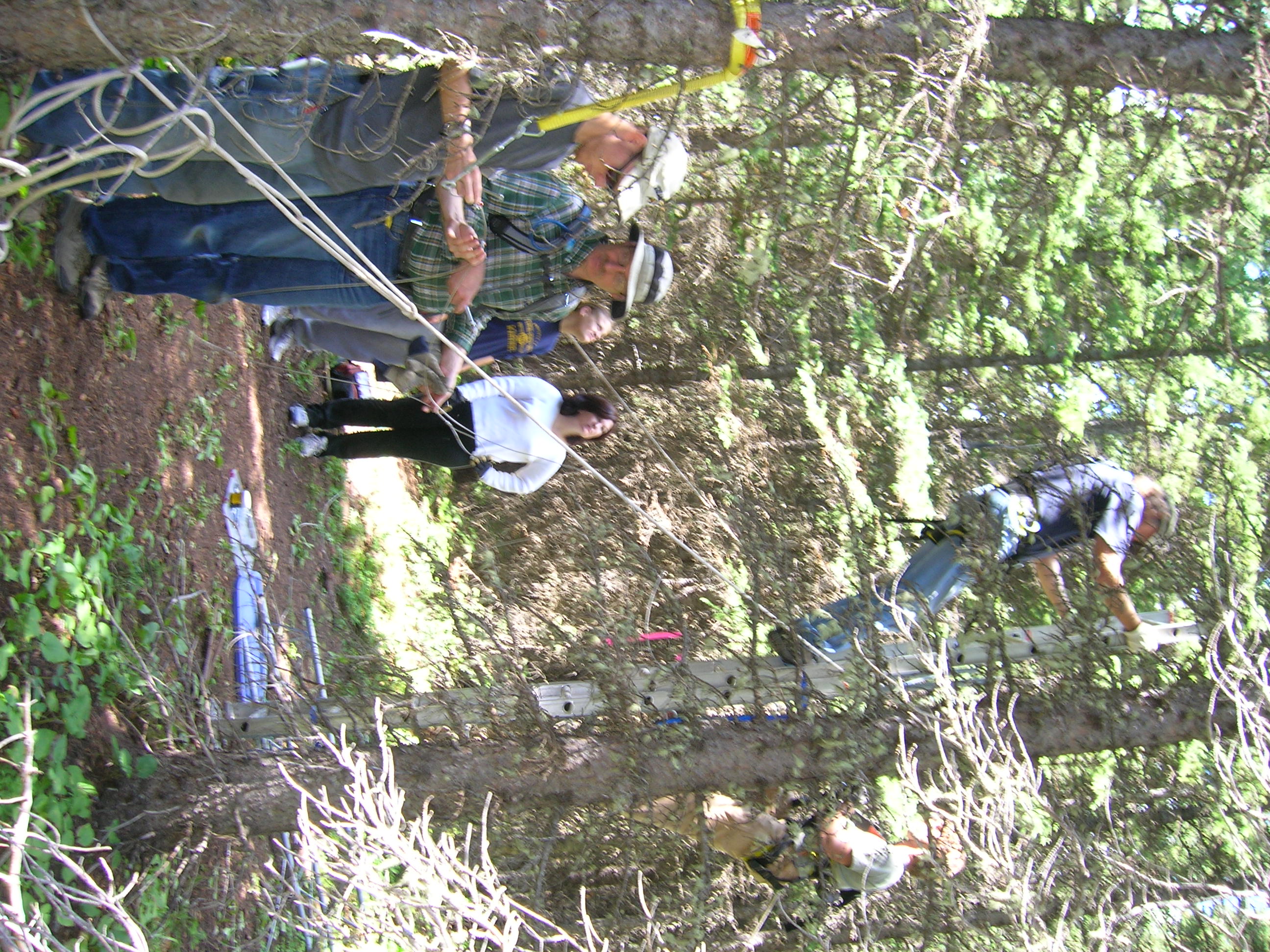
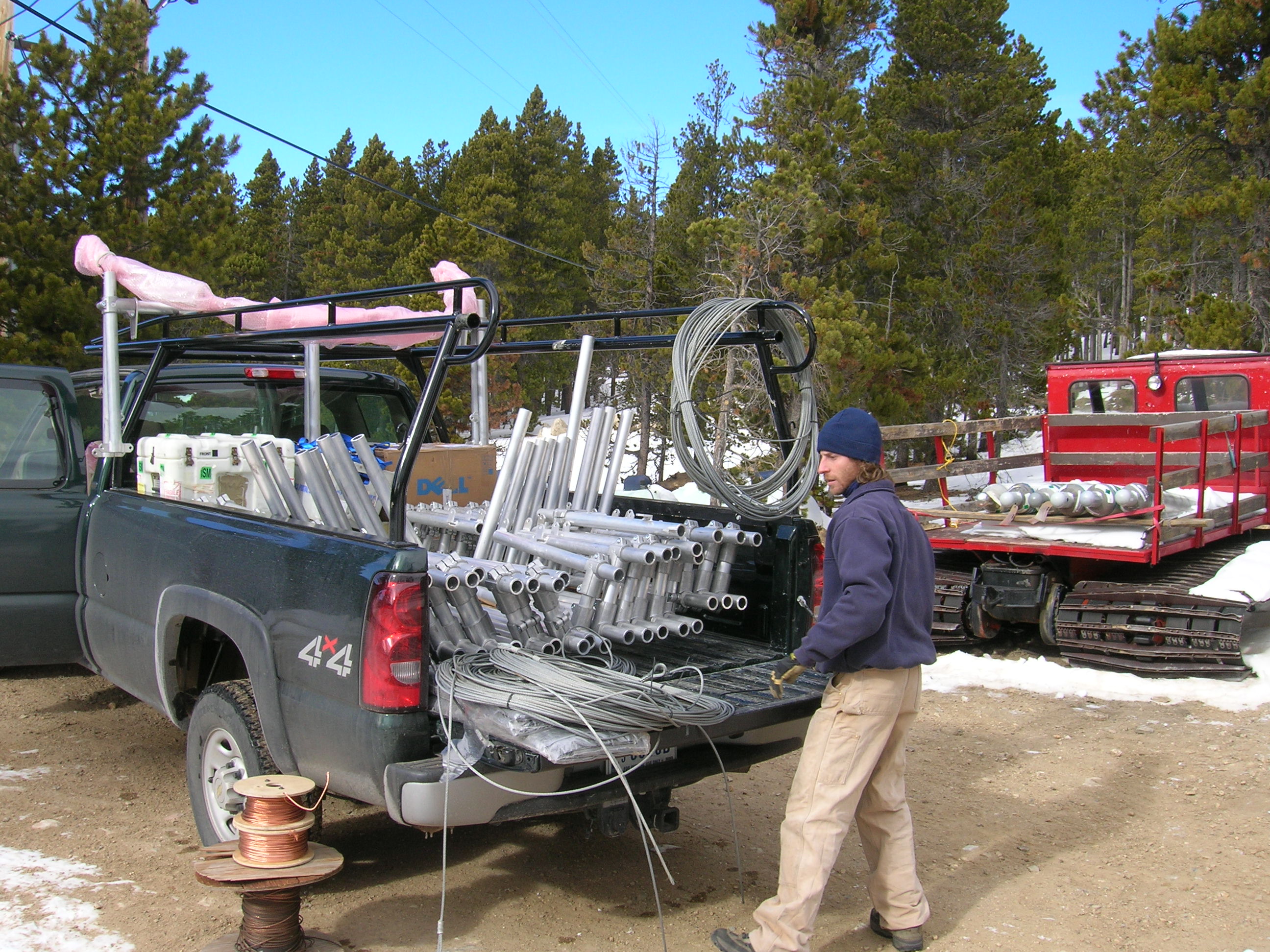
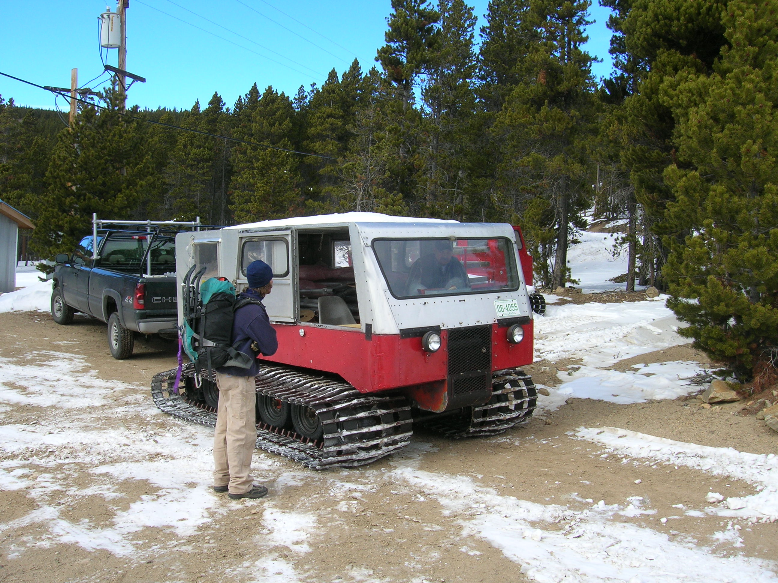
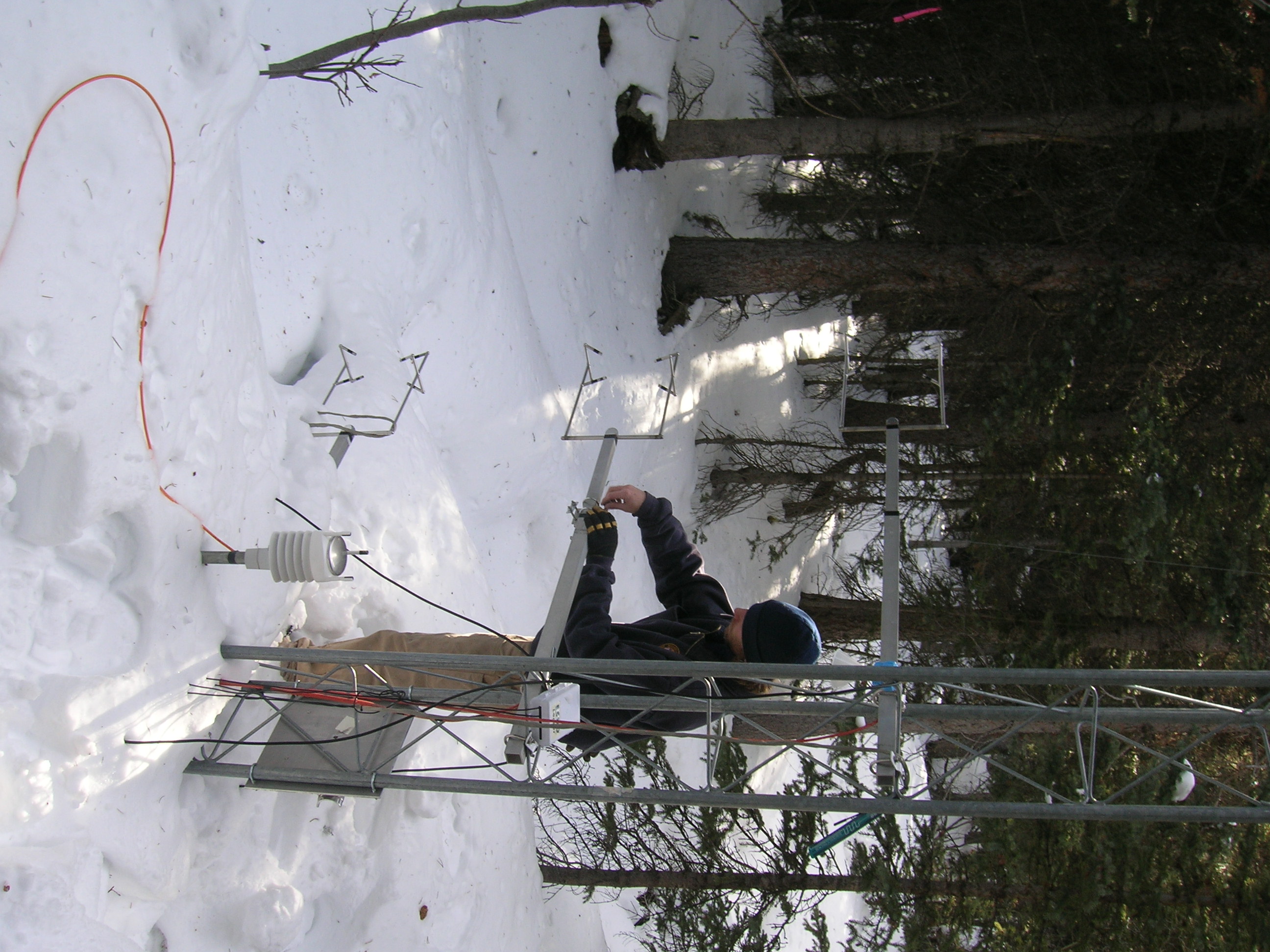
Niwot deployment
In 2006, assembly of a working system at Niwot Ridge began in support of
NIWOT07. An 11-tower, 220m roundtrip,
transect crossing Como Creek about 300m SW of C1 was surveyed in June.
Towers were transported in and erected the last week of July by a crew of
4-7 people. Fixed sensors were deployed in October on the tower nearest
the Creek. Turns were assembled in the Fall and transported by pickup/snowcat
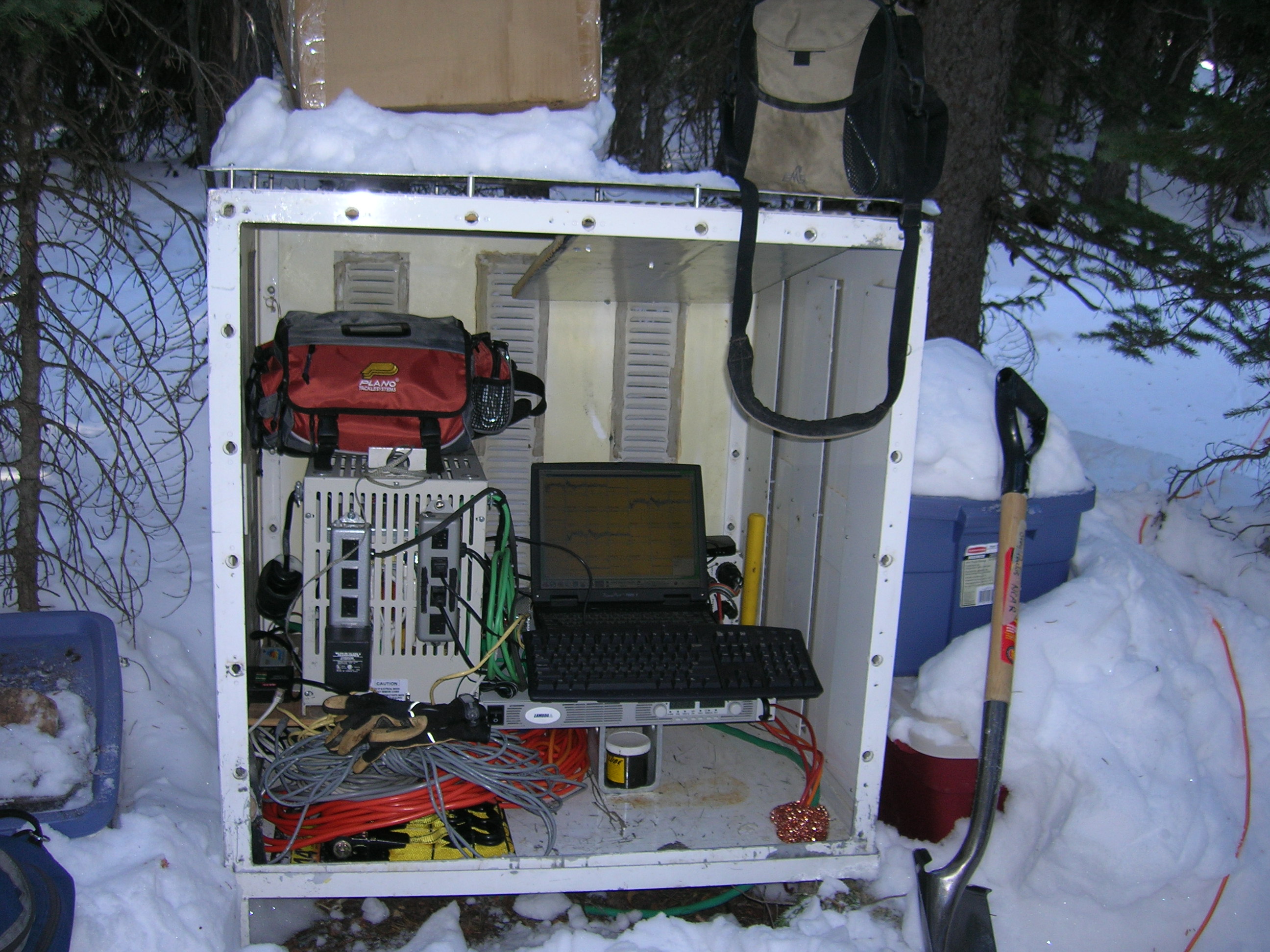
in half a day in early December. TRAM is operated by a laptop and power
supply in a "chem" shelter placed near the Creek.
Some photos:
Further documentation
References
D. Baldocchi, 1984, Ag. and Forest Meteor., 33(2/3), 177-191.
D. Baldocchi, 1984, Ag. and Forest Meteor., 33(3/4), 307-322.
Begue et al., 1996, Ag. and Forest Meteor., 79(1-2), 79-96.
Chen, J.M., et al., 1997, Ag and forest Met, 86 (1-2), 107-125.
Lee, X., and A.T. Black, 1993, "Atmospheric turbulence within and above a
Douglas-Fir stand. Part II: Eddy fluxes of sensible heat and water vapour",
Bound. Layer Meteor., 64, 369-389.
Miyake, M., et al., 1970, "Comparison of turbulent fluxes over water
determined by profile and eddy correlation techniques",
Quart. J. Royal Meteor. Soc., 96, 132-137.
Privette, J.L., et al., 1997, "Estimating spectral albedo and nadir
reflectance through inversion of simple PRDF models with AVHRR/MODIS-like
data", J. Geophys. Res., 102 D24, 29,529-29,542.
This page was prepared by
Steven Oncley,
NCAR Research Technology Facility