Calibration Activities

MJ Mahoney

Last Revised: May 29, 2008

Measuring MTP Pointing Offsets

Introduction

Another article (Pointing an Instrument on an Airborne Platform) describes in great detail the theory behind how MTP pointing corrections are made. MTPs must make brightness temperature measurements at fixed elevation angles with respect to the horizon. The reason for this constraint is simple: retrieval coefficients (RCs) are calculated at specific elevation angles. Therefore, in order to use a given set of  RCs, changes in the aircraft attitude (i..e., yaw, pitch and roll) must be compensated for in real time by changing the MTP scan angles so that brightness temperature measurements are made at the same elevation angles used to calculate RCs. In principal the MTP scan angles (instead of elevation angles) could remain fixed, but then retrieval coefficients would have to be calculated at a potentially infinite number of effective elevation angles, and this (at the present time at least) is computationally unattractive.

Three coordinate systems are involved in determining appropriate MTP scan angles: the horizon or world coordinate system, the aircraft coordinate system and the MTP or instrument coordinate system. While an aircraft's attitude specifies the orientation of its inertial reference system with respect to a horizon or world coordinate system, it is also necessary to know the instruments attitude with respect to the inertial reference system in order to describe how it is oriented with respect to the world coordinate system. The purpose of this brief article is to describe the steps needed to measure the orientation of the MTP with respect to an aircraft's inertial reference system (INS).

Measuring the Pointing Offsets

Because the MTP pointing algorithm uses rotation matrices, it is necessary to express the MTP pointing offsets in a coordinate system that is compatible with the rotation matrices that describe the aircraft attitude with respect to the world coordinate system. Unfortunately, it is not easy to measure the instrument orientation in the same coordinates. To be more specific, if Ya, Pa and Ra describe the aircraft's attitude with respect to the world coordinate system, we would like another set of coordinates Yi, Pi and Ri to describe the instrument's orientation with respect to aircraft's INS platform. As described in the aforementions article, Yi, Pi and Ri cannot be measured directly; rather, what can be measured are angles on the edges of the Sensor Unit that are roll-like, pitch-like and yaw-like; that is, the edges that are most like the aircraft axes about roll, pitch and yaw occur. Figure 1a for example is on the edge of the Sensor Unit that is pointing forward, which is the roll-like axis, but the angle measured is B, the pitch-like angle.


Pitch-like
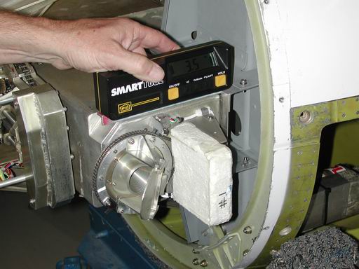
a) Roll-like axis (measure pitch-like angle B=-3.5 degrees)
Roll-like
b) Pitch-like axis (measure roll-like angle  T=4.6 degrees)
yaw-like
c) Yaw-like axis (measure angle of normal Z=87.1 degrees)
x
d) Pointing bar
Figure 1. Measurement of the roll-, pitch- and yaw-like axes on the NASA WB-57 left spearpod are shown in panels a), b) and c). The  scan  mirror  extension and bar are shown in panel d).

TBZ_to_YPR_WB57.MCD
BZT-YPR1-WB.png
BZT-YPR2-WB.png

TBZ_to_YPR_ER2_SU1.MCD


BZT-YPR1.png
BZT-YPR2.png


Previous  |  Next  |  Index  |