ATI sonic anemometers
ATI manual
Introduction
The following discussion all refers to
Applied Technologies, Inc. sonic anemometers with the electonics in
the booms. NCAR/ATD/SSSF used older-style ATI and UW anemometers with the
electronics in a separate box prior to SHEBA (1997). The description below
of the arrays is still applicable for these earlier arrays, but the maintenance
and other mechanical issues changed. See here
for some information on these earlier probes.
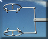
K-probe

This probe has 3 orthogonal, non-intersecting, paths and is called a "K" probe
after the initial design by Chandran Kaimal.
The pathlength is 15 cm.
The idea of this probe is that each path would have good exposure to the air
flow which is unaffected by the other paths. Thus, the flow distortion
for this array would be due simply to that of each single path, for which
wind tunnel data were available.
Kaimal et al. (1990) demonstrated this with a "flipped and rotated" test in
the field and found residual errors in wind speed of about 2%, using a
maximum 18% correction for each path.
We've taken similar data at our Marshall field site.
Our best fit uses a maximum 20% correction for each path, but still reduces
the overall speed error to only about 5%. This probably is due to the
variation of sampling statistics as a function of height. The Kaimal
data were taken on the BAO at a height of 22m and our data was taken at a
height of ~5m(?). Since the Marshall data are more representative of our
normal operations, we operate the K-probes with a maximum 20% single path
correction but with no further correction for flow distortion effects from
the array.
NUW probe

This probe is built by NCAR, based on a design initially conceived of by
Joost Businger and constructed at the University of Washington (Zhang et al.,
1986) -- hence the name "New U.W.", or "NUW".
The idea of this probe is to have no objects upwind of a path, including
the transducer itself, which requires that no path be oriented horizontally.
Of course, one "strut" must be used to physically connect the top and bottom
parts of the array, so one wind direction must considered "bad".
Fortunately, flow from this direction also goes through the tower that the
sensor is mounted on, so only this direction must be ignored.
A pathlength of 20 cm was used in the original UW probes and was duplicated in
the NUW probes to allow the earlier flow distortion tests to be directly
applied.
This probe has been tested in a large EPA wind tunnel and in the field and
found to have minimal flow distortion, except when the wind direction is
within 20 degrees of the back of the array.
Thus, we operate it with no corrections for flow distortion and reject data
from directions corresponding to flow from the tower.
The NUW arrays are not perfectly built, despite the use of a jig when they
are epoxied together. Thus, the array geometry has to be measured whenever
the arrays are rebuilt. I have found that using spherical balls with
a precisely-drilled hole for the transducer to fit inside provides a good
reference surface to allow the dimensions to be obtained using a larger
vernier caliper. From a measurement of all combinations of distances between
transducers, it is possible to get the angles to within ~0.2 degrees and
an estimate of the closure of the measurements (generally to ~2mm).
A-probe
This is a new "ring" sonic developed by ATI. The electronics are identical
to a K-probe.
Like the K-probe, the pathlength is 15 cm.
Like the Gill, CSAT3, and UW probes, it has 3 paths that are separated by
120 degrees in azimuth and pitch angles all 60 degrees.
Since one path is oriented perpendicular to the boom, this array is symmetric
to being flipped upside-down (which also makes it cheaper to manufacture, since
the same piece can be used for the top and bottom of the array).
ATI extended their operating code to apply the appropriate matrix rotations
(and path curvature corrections, I think) to deal with this non-orthogonal
array, so our NUW sonics also use this code.
We have inadvertently taken data with the NUW probes using the rotation
matrix for an A probe, so its rotation matrix is recorded
here.
Level sensors
ATI offers an option to add level sensors to their sonic anemometers to help
in orienting the sensor and/or data. We had a long
discussion on whether to add these to all of our
probes (initially we only had 2 arrays with levels) and decided not to
add level sensors to the rest of our arrays. For the data from those two
sensors, a description of how to interpret the data is given
here.
Spike detection
The current generation of ATI sonics have significantly improved the quality
of the signal, so that spikes in the data are much less of a problem. The
ATI electronics have spike detection built in (see
description), but we have found that temperature jumps due to daytime
convection in the atmospheric surface layer gave false detections. Thus,
we currently turn this internal spike detection off.
However, we do process the data using a more sophisticated
despiking algorithm, which looks at the 10 or 20 sps data from the sonic.
In most cases, we use the output of this algorithm just to flag potentially bad
data, though we have implemented the algorithm to allow us to replace these
values as well.
Maintenance
I have a checklist of how to service these
anemometers, including transducer replacement, NUW array reconstruction,
calibration, and software reconfiguration. Any major maintenance should be
logged in Service.txt, so that we can keep track
of the history of each sensor.
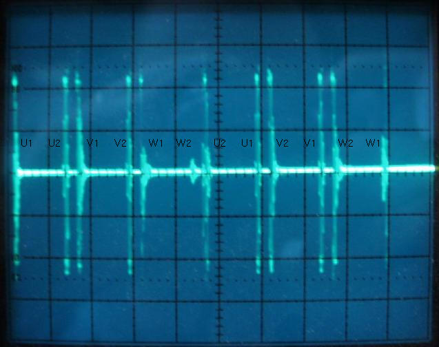
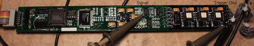
To check the ATI sonic on the bench, I have a view of the
oscilliscope display for a normal ATI sonic
when the oscilliscope probes are connected to
test points on the ATI electronics board,
horizontal sweep at 0.5ms/div and vertical scale at 2V/div.
This shows the U1 transducer sending an accoustic pulse which is received
about 700us later by U2 and then a wait of about 200us before V1 transmits to
V2, etc. This cycle repeats every 5 ms. Note that the amplitude of the
received signal is about 5 V_half-peak. If it is significantly lower,
the transmit and/or receive transducer should be replaced. Also note that
a 'scope with delayed sweep capability will allow you to look at the pulse
shapes in detail.
References
Kaimal, J.C., J.E. Gaynor, H.A. Zimmerman, and G.A. Zimmerman, 1990,
"Minimizing flow distortion errors in a sonic anemometer",
Boundary-Layer Meteor., 53, 103-115.
Zhang, S.F, J.C. Wyngaard, J.A. Businger, and S.P. Oncley, 1986,
"Response characteristics of the U. W. sonic anemometer", J. Atmos.
Ocean. Tech., 3, 315-323.